Pedal Torque
Table of contents
- Introduction
- Warnings
- Required tools
- Supported torque sensor types
- Torque sensor input & wiring
- Pedal torque sensor setup
- Configuration parameters
- Troubleshooting
1 – Introduction
A torque sensor measures the force a rider is applying to the pedals and commands a proportional amount of motor assistance. Compared with pedal cadence only, where the output power is decoupled from pedal input power, a torque sensor ties the motor output power to the input pedal force. This provides an amplified analog bike ride feel.
Different torque sensor types exist, axle type and the more common pedal type.
- Pedal torque sensors refer to sensors that have integrated torque and cadence sensor. The cadence sensor needs to be configured to actually start and stop a vehicle. The motor will not be enabled until the pedals are rotated. Pedal torque sensors need the specific offset to be programmed.
- Axle torque sensors or any torque sensor without an integrated pedal sensor need to be configured to not start a vehicle without pedalling. In the absence of a cadence sensor, the vehicle has to use the rolling start feature so that the motor will not be enabled until the vehicle is at a minimum speed (this assumes the pedal got it to this speed). We automatically measure axle torque sensors offset during power-up. This assumes the user is not putting pressure on the pedals during power-up.
This section will guide you through setting up your pedal torque sensor.
See Axle Torque sensors to set up your non-pedal type torque sensor.
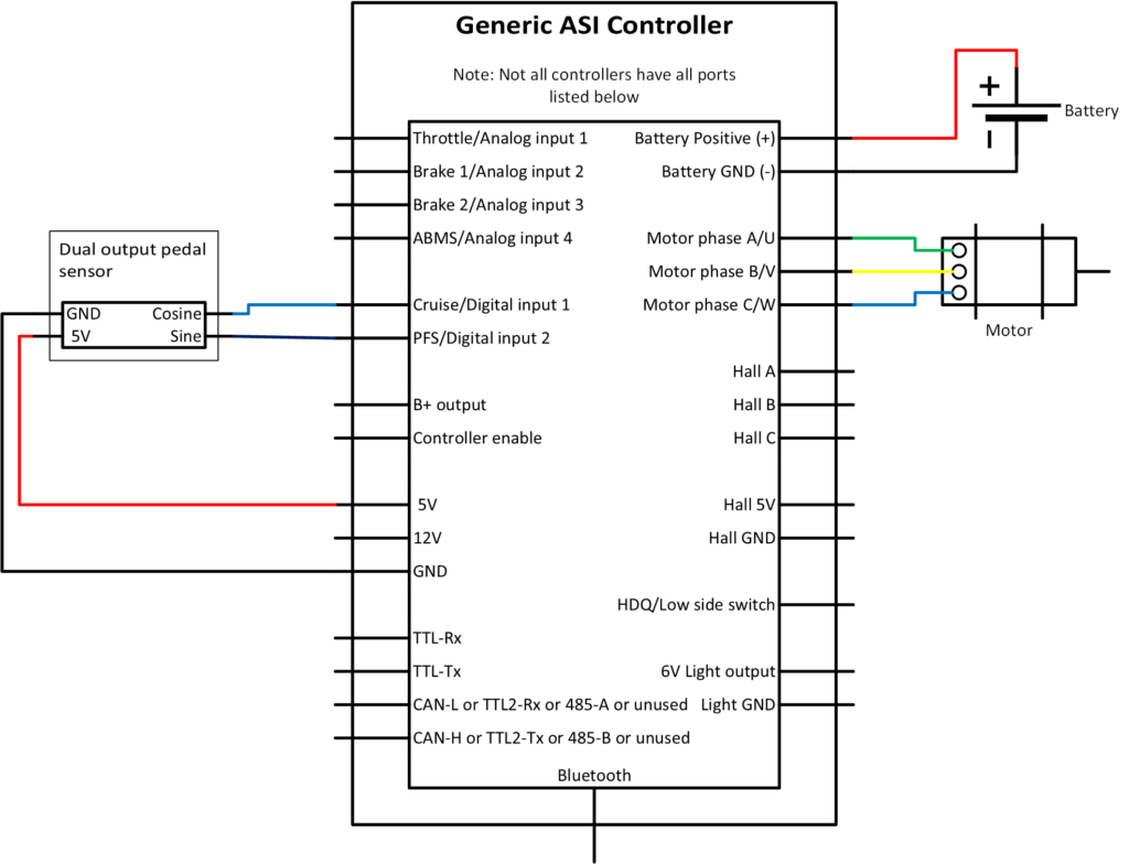
2 – Warnings
ATTENTION – Indicates a step or procedure required before proceeding to the next step or page.
CAUTION – Indicates a potentially hazardous situation which may result in minor injury or product damage.
WARNING – Indicates a Hazardous situation which if not avoided will result in serious injury/death to person(s) or damage to product and/or equipment.
TIP – Indicates a helpful Tip to make things easier and faster.
3 – Required tools
- Appropriate personal protective equipment (PPE) as required(e.g. Safety glasses, gloves, etc.)
- ASI BACDoor software
- 22 AWG Wire strippers (eMobility)
- 18 AWG Wire strippers (high power)
- Vehicle stand, or motor stand to securely support the vehicle or motor drive wheel off the ground for testing (e.g. Bike stand, jack stands, etc.)
4 – Supported torque sensor types
The following pedal torque sensor types are supported:
- Quadrature torque with (Sine/Cosine) digital pedal cadence
- Single Hall torque sensor (e.g.: Methode)
- Single Hall reverse torque sensor (e.g., LDS)
The following axle torque sensor types are supported:
- 0-5V analog signal
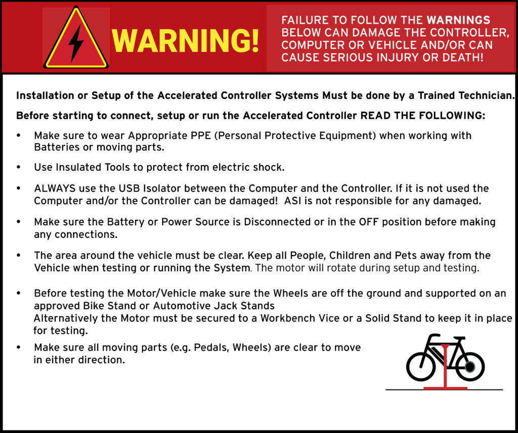
5 – Torque sensor input & wiring
A torque sensor typically has 3 wires: 5V or 12V power, GND, and a signal wire. The signal can be wired to use any analog input, typically Throttle/Analog input 1. If the sensor is axle type, the signal must be connected to Throttle/Analog input 1.
If the torque sensor is a pedal type, the power and ground will be shared with the integrated cadence sensor. See below for the 2 cadence sensor output wiring examples.
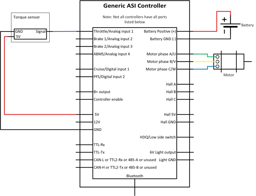
The Example 1: Single-output pedal cadence sensor
Single output single or dual Hall pedal sensors typically have 3 wires: 5V or 12V, GND and signal. The signal wire must be wired to PFS/Digital input 2.
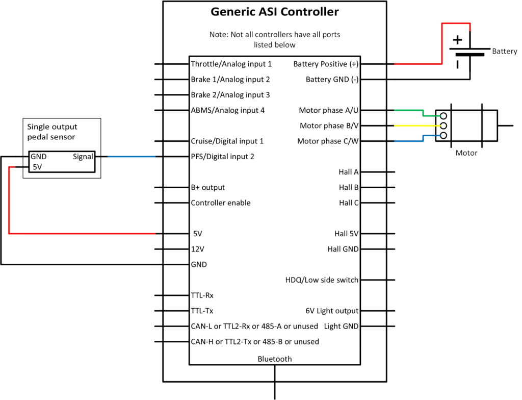
Example 2: Two output pedal cadence sensor (Quadrature speed)
Two signal pedal speed sensors typically have 4 wires: 5V or 12V, GND, Sine signal and Cosine Signal. The Sine signal must be wired to PFS/Digital input 2 and the Cosine signal to Cruise/Digital input 1.
6 – Pedal torque sensor setup
WARNING – Ensure vehicle is secured in-case the motor engages unexpectedly while manually configuring your pedal sensor.
TIP – Hover over the information icon for parameter location in BACDoor™ shorthand.
TIP – Make a backup copy of the parameter file often by saving it to file as shown before. It can be sent to ASI for support or you can revert if strange behaviour occurs.
With the pedal torque sensor connected to the controller:
- Set Control command source to 0 (serial stream) to prevent the motor from accidentally spinning while manually setting the pedal torque sensor.
- Enable the eBike flag, bit 10 under communications configuration vector, if not already.
- Set Pedal sensor type to your pedal torque sensor type.
- These instructions apply to options 2 (FAG), 3 (Quadrature torque), 7 (single hall torque sensor (methode)) and 8 (single hall torque sensor (LDS)).
- Enter your total combined pedal signal rising edges into Pedal speed sensor pulses per revolution.
- Set your Torque sensor voltage source to your torque signal input source.
- Poll the selected voltage input source and apply load to the torque sensor to verify the input source voltage is wired correctly and responding to changes in torque input.
- Note the base voltage (no torque applied), and whether the voltage increases or decreases with torque on the sensor.
- Set the Torque sensor offset voltage per your torque sensor datasheet. If unknown, use the nominal input voltage source value noted from step #6 above.
- Set the Torque sensor gain (Newton-meters per Volt [N-m/V]) per your torque sensor datasheet. Set it negative if your voltage drops with torque (noted in step #6 above), or else the controller will calculate negative gain.
- If your datasheet provides Kilograms-force per volt [kg.F/V]. It can be converted by multiplying by gravity (9.81 m/s^2) and the pedal arm length (generally 0.175m) to [N-m/V].
- If your datasheet provides V/Nm, divide 1 by the value given to invert the units
- Set the Pedalec power gain to 1 for 1:1 power gain relative to measured torque to start testing with.
- Set the Control command source to Pedal sensor or throttle OR pedal sensor, as appropriate.
- Ensure you do not have any faults, and test that when rotating the pedals in the forward direction, the motor spins up, and when no longer rotating or spinning the pedals backwards the motor coasts to a stop. If not see troubleshooting.
- Save to flash to save the parameters to the controller.
- Perform the Average pedal speed test to ensure the pedal cadence sensor is set up correctly.
- Check if the torque output of the sensor configured and is working properly. Add a small amount of resistance to the motored wheel either using a bike trainer or the brakes and then pedal in the forward direction at as constant a cadence as possible. Observe that the average pedal torque increases/decreases with the addition/subtracting of resistance provided by the brake.
Average pedal speed test
To check if the pedal output is configured and is working properly. Operating the pedals in the forward direction and examine the value of the average pedal speed parameter. If the value is positive when pedalling forward and negative when pedalling backwards, the wiring is correct. If the average pedal speed values are reversed, then the wires connected to the PFS/Digital input 2 and Cruise/Digital input 1 inputs need to be reversed. If the average pedal speed value is erratic at a constant pedal cadence then there is likely an issue with the wiring.
Torque sensor fine-tuning of feel and adjustment parameters are explained in Section 4 – Ride Performance: Pedal and torque sensor tuning.
7 – Configuration parameters
Command inputs configuration
The following parameter is key to configure the main method by which a vehicle is commanded to move.
| Name | Description | Units | Address |
| 208 |
Pedal input configuration
The minimum information required to set up a pedal sensor is the sensor type and the pulses per revolution.
| Name | Description | Units | Address |
| 211 | |||
| 234 | |||
| 183 | |||
| 179 | |||
| 349 | |||
| 182 | |||
| 178 |
Torque input parameter
This value can be monitored to ensure your torque sensor is wired correctly and the controller is measuring the input torque.
| Name | Description | Units | Address |
| 332 |
Command levels
The motor command levels can be monitored with the parameters below.
| Name | Description | Units | Address |
| 335 | |||
| 336 |
eBike flags
eBike flags are a convenient parameter to monitor when developing a drive system. They indicate what the controller state is when any input is activated.
| Name | Description | Units | Address |
| 327 |
8 – Troubleshooting
8.1 – I have no motor assistance?
8.1.1 – Vehicle maximum speed not set in speed limited modes
If you are in a speed-limited Speed regulator mode (e.g.: speed or torque mode with speed limiting), you must set your Vehicle maximum speed (Race mode PAS max speed) and Vehicle maximum speed (Street mode PAS max speed) to non-zero values accordingly.
8.1.2 – Rated motor power not set for alternative power modes
Set Rated motor power (Race mode PAS power) and Rated motor power (Street mode PAS power) to your rated motor power for modes used.
8.1.3 – Negative torque
Some sensors voltage drops with applied torque, for these sensors the Pedalec torque gain value must be negative to calculate a resulting positive average pedal torque. Commanding assistance from the motor.
8.1.4 – Assist level
If you have chosen an Assist mode source other than 0 (none), set it to 0 and verify whether you have any motor assistance or not. If you do, likely the assist mode source is not set up correctly and is limiting some or all power and enforcing a speed limit below your testing threshold.
8.1.5 – Negative cadence
If you are getting a negative cadence when pedalling forward and are getting a positive cadence and likely motor assistance when pedalling in reverse, you’ve chosen the wrong pedal cadence sensor type. The solution is to choose the reverse or if reverse chose the normal pedal sensor type. I.e. if you chose single Hall reverse and your cadence is negative, chose single Hall.
8.1.6 – Ebike flag not set in communications configuration vector
Enable communications configuration vector bit 10 (Enable Ebike) to enable Pedal sensors.
8.2 – Brake and cutout enabled
For example, eBike bit 1: Cutout enabled prevents the motor from engaging, this is generally coupled with eBike bit 0: Brake enabled. This means the brake is enabled and is causing the motor to cutout. Solutions include:
- Disconnect your brakes, they may be pulling the brake voltage out of range.
- Set the Cutoff brake sensor source to out of range if not already to stop reading the external brake sensor source and clear the two eBike flags (cutout and brake).
- Poll the chosen Cutout brake sensor source voltage, ensure it is above the Analogue brake full voltage value. If for example, your voltage source is 3.5V and the analogue brake full voltage is 4V, the cutout will be enabled.
8.3 – My motor engages when pedalling backwards, but not forwards
Our controller may be interpreting the forward pedal cadence signal as if the pedals are rotating in the reverse direction and thus not providing any motor assist. Switch your Pedal sensor type to reverse type or from reverse type to standard type. For example, switch from single Hall (0) to single hall reverse (6).
8.4 – Ebike flag not set in communications configuration vector
Enable communications configuration vector bit 10 (Enable Ebike) to enable Pedal sensors.