Using BACDoor™ PC
Table of contents
- Introduction
- Installing the application
- Navigating the application
- Parameter location shorthand
- Updating firmware
- Saving and uploading parameter files
- Analyzing parameters
- Updating the object dictionary
- Datalogging
- “Scoping” using the built-in oscilloscope
Introduction
BACDoor™ PC is designed to give users the complete ability to adjust all the controller parameters and functions directly from their computer. Due to the amount of low-level access to the controller this app gives, it is NOT provided to end-users.
Current software version: 1.16.1.0
Installing the application
- Software supplied selectively by request only to ASI OEM Customers and Authorized Dealers, please contact support@acceleratedsystems.com
- Supported OS’s include – Windows Vista, Windows 7, Windows 8, Windows 8.1 (both 32 and 64 bit), Windows 10
- You must be an administrator to install.
- The software cannot be installed from a network location.
- Regional settings must be US English.
- Internet access may be required if .NET needs to be updated
Install the supplied copy of BacDoor Setup.msi (not .exe) to your PC. Note where it is installed on your hard drive as you may need to access this folder later to update files or access generated datalogs, for example. Generally, it is saved here: C:\Accelerated Systems\BacDoor
BACDoor™ PC requires that you have Microsoft Visual C++ 2015-2019 Redistributable (x86) installed if it is not already in order to bootload firmware. It is available here.
BAC controllers require the FTDI TTL 232 driver to communicate. If this does not auto-install when you connect the controller to your PC while the controller is powered on. Download and install the USB driver, available here.
Navigating the application
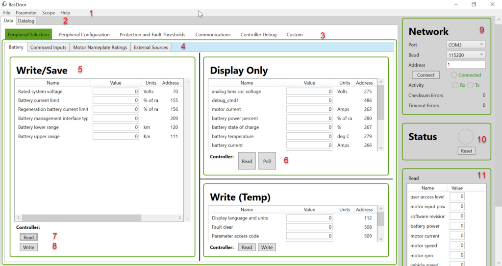
1 – Menu Bar
In Menu, you will find these drop-down menus: File, Parameter, Scope, Help.
A) File
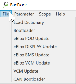
Load Dictionary: Deprecated function. See Updating the object dictionary for how to update the dictionary.
Bootloader: Pushes .ehx files to the controller and saves them to flash. This could be either new firmware or encrypted parameter files.
eBlox POD Update: Updates ASI POD firmware via the controller
eBlox DISPLAY Update: Updates ASI Display firmware via the controller
eBlox BMS Update: Updates ASI BMS firmware via the controller
eBlox VCM Update: Updates ASI VCM firmware via the controller
VCM Update:
CAN Bootloader:
B) Parameter
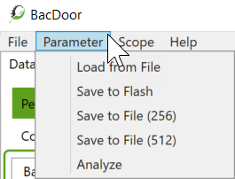
Load from File: Loads a parameter file, .XML, from file to the controller
Save to Flash: Saves the parameters to the controller
Save to File (256): Saves parameters from the controller to the file. Meant for software revision 5.xxx controllers.
Save to File (512): Saves parameters from the controller to the file. Meant for software revision 6.xxx controllers.
Analyze: Loads, .XML, parameter files to BACDoor™ to analyze when not connected to a controller.
C) Scope
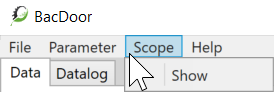
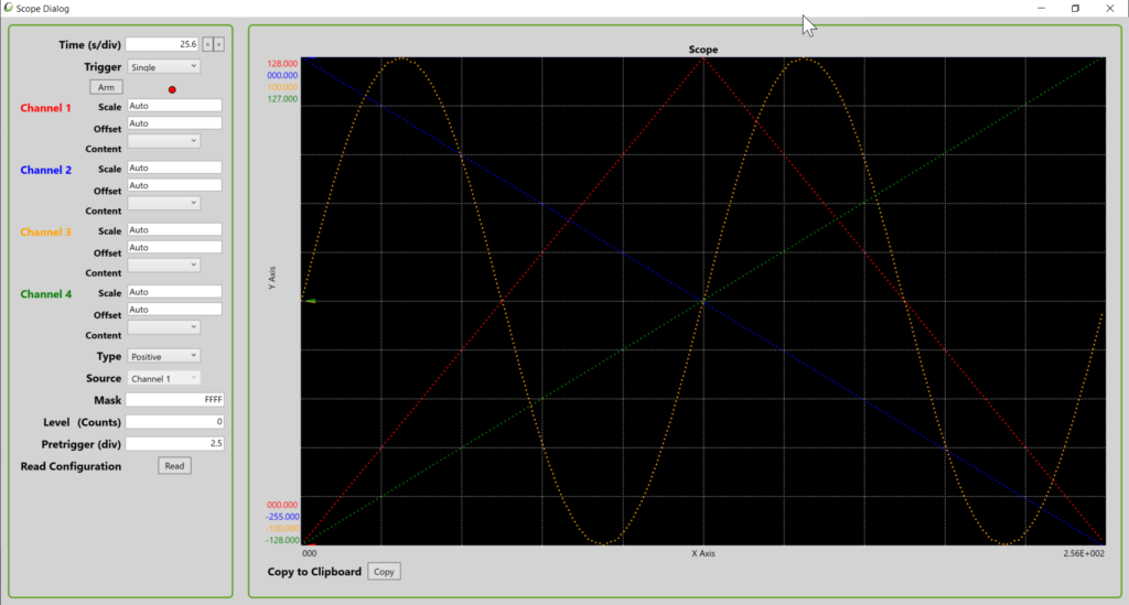
Show: This will pop-up the Scope Dialog screen, for more information on scoping go to “Scoping” using the built-in oscilloscope below.
D) Help
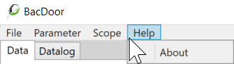
About: BACDoor™ description and software version
2 – Submenu Bar
Submenu bar includes Data or Datalog
On the Data screen, you see all of the pages, tabs and sections from which you can read, write, and change parameters on the controller or file being analyzed.
On the Datalog screen, is where you set up and run your datalog. Got to Datalogging below for more information.
3 – Tabs
Tabs are core groups of parameter sets with an overarching theme. Tabs include:
- Peripheral Selection
- Peripheral Configuration
- Protection and Fault Thresholds
- Communications
- Controller Debug
- Custom
4 – Pages
Pages are unique to each tab, with each page having a subset of parameters linked to the overarching tab. Your layout may differ.
Peripheral Selection page includes the following tabs:
- Battery
- Command Inputs
- Motor Nameplate Ratings
- External Sources
Peripheral Configuration page includes:
- Throttle
- Brakes
- Assist Mode
- Battery
- Axle Torque Sensor
- Pedal Speed Sensor
- Pedal Torque Sensor
- Vehicle
- Basic Motor (Sensored)
- Basic Motor (Sensorless)
- Anti Theft
- Advanced Motor
- Angle Sensor
Protection and Fault Thresholds page includes:
- Battery
- Motor
- Controller
Communications page includes:
- Serial Communications
- CAN RPDO1,2
- CAN TPDO1,2
- CAN TPDO 3,4
Controller Debug page includes:
- Bridge
- Control Loops & Tuning
- Filters
- A2D Gains
- Test
- Test2
- ISR Execution Times
- OTP/CRCs/Versions
- MotorModel
Custom page includes:
- Speed/Power
- Ramp Times
- Features/Faults
- Accelerometer
5 – Sections
Sections include Write/Save, Display Only, and Write (Temp).
You can add parameters to any of these sections by right-clicking and selecting add parameter and selecting the parameter you want to add if it is missing. You can also remove parameters the same way.
Hovering over a parameter name will popup its definition and if applicable it’s bit definitions.
Bits are read right to left, bit 0 is the rightmost bit. Hovering over a bit will bring up the definition of that specific bit.
In Write/Save, is where you can edit and write parameters that will immediately affect the controller when written but are not yet saved to flash. You must save to flash to write these permanently to the controller.
In Display Only, is where you view and read values from various parameters, it can be static or live depending on if you have read the parameters (snap-shot in time), or selected poll for live updating of your values.
In Write (Temp), is where you can write parameters which you do not want to save or flash, but perform temporary functions such as remote motor commands.
In these sections, you can press <Enter> on your keyboard after every entry to a parameter to write it, or press Write once you have changed all the parameters you wanted to change. If you do not do this, when you change pages or tabs the values you entered will not be saved.
6 – Poll
The Poll button provides a low-refresh rate live feed of the parameters within the Display Only section. The values will respond to changes, inputs, and outputs occurring to the controller when connected.
7 – Read
The Read button will read the values to the parameters in its respective window at that moment in time when you press the button. Displaying them for your interpretation. This is not live, but a snap-shot of their values when you pressed the Read button.
8 – Write
The Write button temporarily writes the values entered in each parameter to the controller, but you must still select save to flash for the changes made to survive a power cycling of the controller.
9 – Network
The Network is where you can select which port is connected to the controller. Generally, if you’ve connected the controller to your computer, the controller is ON and then you open the application it will auto-select the right port. Otherwise, you may need to try going through the available ports, the easiest way to do this is by disconnecting all your other peripherals to shorten the list.
You can select the Baud rate (default from us is 115200, otherwise it defaults to 9600). Should not need adjusting unless your baud rate was changed in your parameters.
Clicking Connect with the Port and Baud rate set will connect to your controller. The Connected light should flash along with the Rx and Tx Activity lights.
Checksum Errors
Timeout Errors
10 – Status
The Status will change colour when there is an issue with your controllers such as a warning or a fault. Hovering over the status light will show you what the issue is.
11 – Data
Read data in the bottom right of the frame shows a select series of commonly read parameters that are continuously polled. A quick way to check the health of your system and watch the input and output values for example.
Parameter location shorthand
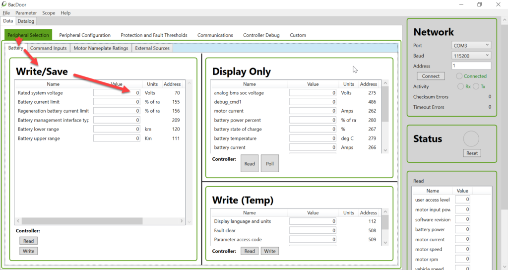
Parameter locations in the application can be quickly referred to by this shorthand: [PC BACDoor|Tab|Page|Section|Parameter]
Example: [PC BACDoor|Peripheral Selection|Battery|Write/Save|Rated system voltage] refers to the parameter, Rated system voltage, location as shown in the following image.
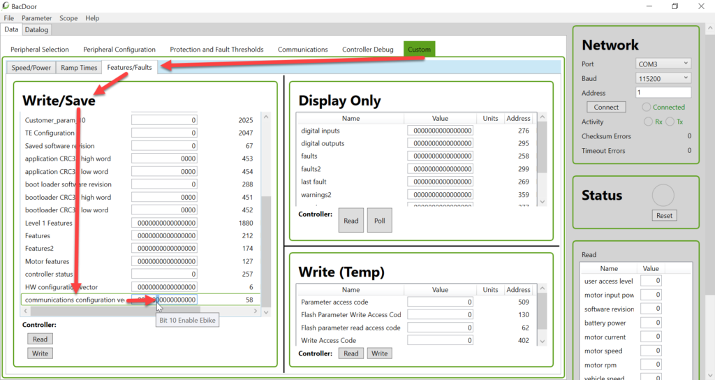
Parameter bits can be called out as follows: [PC BACDoor|Tab|Page|Section|Parameter:Bit]
Example: [PC BACDoor|Custom|Features/Faults|Write/Save|communications configuration vector: Bit 10 Enable eBike] refers to bit 10 (read from the right-most, bit 0, counting up to the left-most bit, the highest bit) of the communications configuration vector as shown in the following image.
Updating firmware
BACDoor™ PC requires that you have Microsoft Visual C++ 2015-2019 Redistributable (x86) installed to bootload firmware. It is available here.
Controller firmware can be updated using encrypted hex files provided by ASI. Firmware files (.ehx) are loaded onto the controller via the Bootloader function in the File drop-down menu.
Though the software should not be able to push the wrong firmware. Caution must be taken and you shouldn’t try to push the wrong firmware series to the controller and brick it. To prevent this, confirm what your controller’s software revision is. This can be found in the Data section when connected to your controller.
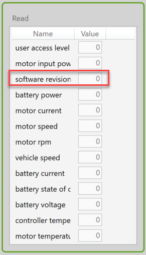
If you have software revision 5.xxx on your functioning controller, only 5 series software shall be used.
If you have software revision 6.xxx on your functioning controller, only 6 series software shall be used.
Troubleshooting
If you cannot load new firmware to the controller, confirm that you have Microsoft Visual C++ 2015-2019 Redistributable (x86) installed if it is not already. It is available here.
Saving and uploading parameter files
Parameters files (.xml) can be saved from your controller to your hard drive or uploaded from your hard drive to your controller.
To save parameters to file, click the Parameter drop-down menu and then select Save to File (256) for controller software version 5.xxx. Select Save to File (512) for controller software version 6.xxx.
The software version can be found in the Data section when connected to your controller. See the image above in Updating Firmware.
Analyzing parameters
Parameter files saved on your computer can be analyzed in BACDoor™ by going to the Parameter drop-down menu, selecting Analyze, and opening your .XML parameter file.
Once done looking at your parameters, you must close and reopen BACDoor™, or open a second instance of BACDoor™ to connect to your controller.
Opening more than one instance of BACDoor™ can be very useful. For example, you can connect on one, and analyze in the other…
Updating the object dictionary
Close BACDoor™. Go to C:\Accelerated Systems\BacDoor and copy ” “ASIObjectDictionary.xml” and save it elsewhere.
Copy the desired version of the “ASIObjectDictionary.xml” file into C:\Accelerated Systems\BacDoor and replace the existing “ASIObjectDictionary.xml”. Reopen BACDoor™ to use the new Object Dictionary.
Datalogging
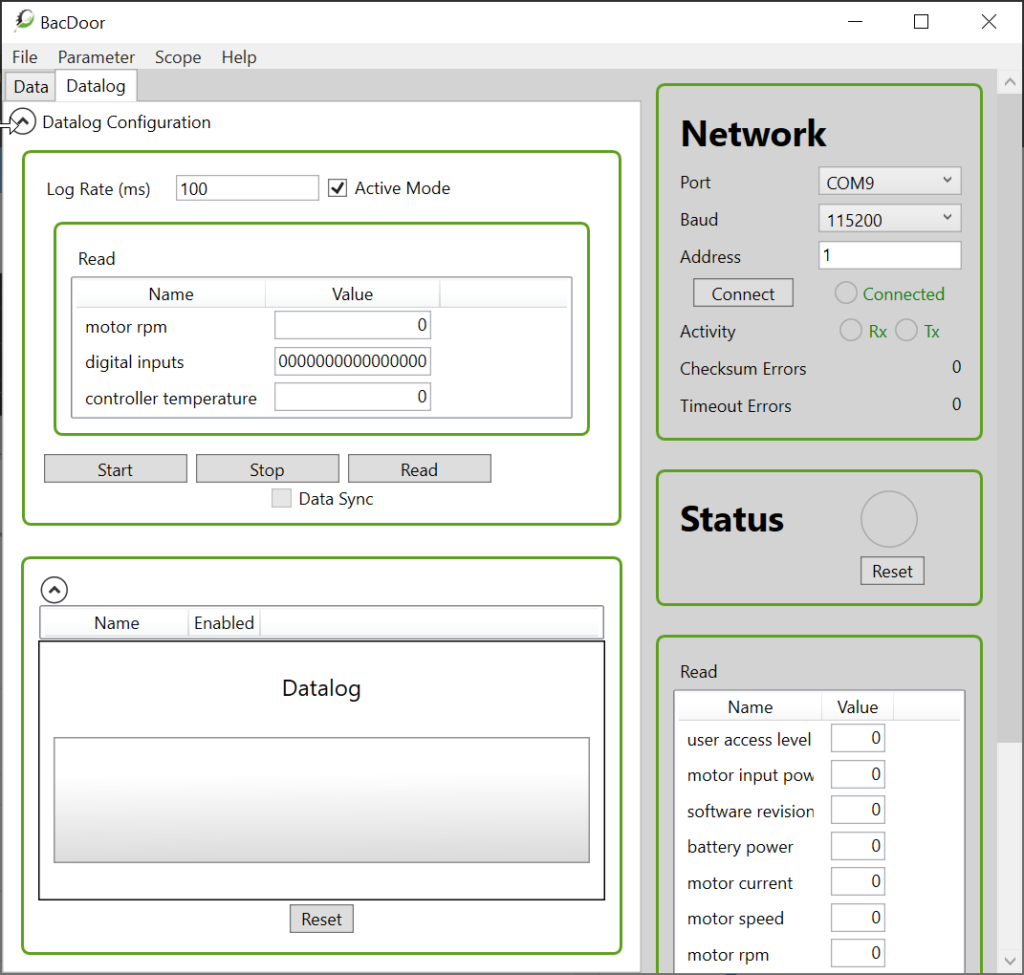
Controller values can be datalogued using the Datalog feature on the sub-menu. In Datalog you can select the Log Rate in ms. In the Read Section you can add and remove parameters which you want to log. Clicking the Read Button will read the instantaneous values of the controller while connected. Clicking the Start button will start the datalogue and run it until you press Stop.
Note: Be sure to press Disable in the right column so that you do not datalog the data below Network and Status.
Note 2: Datalogging may take ~10 seconds after pressing start to begin actively logging data.
The output file will appear in your file browser in C:\Accelerated Systems\BacDoor as a .csv file titled “ASI_Datalog_DD_MM_YYYY_HH_MM_SS.csv.” Where in the file name; DD is the day, MM is the month, YYYY is the year, HH is the hour (24-hour clock), MM is the minute, and SS is the second that you started the log.
“Scoping” using the built-in oscilloscope