Peripheral Inputs – General Overview
Table of contents
- Introduction
- Configuration & programming
- Control command source
- Input specifications
- Supported peripherals
- Peripheral input sources
- Application configuration examples
- Pinout tables
Introduction
Having completed the core function of the controller, basic motor control, we need to now manually control the motor characteristics via various input types and sources.
On this page, we present best practices for connecting and programming your peripheral inputs. Our controller’s analog and digital signal input specifications are from our product sheets. Our currently supported generic peripheral types and our recommended controller input pin. Lastly, several product configuration examples.
Warnings
The following colour blocks may be used to draw your attention to things requiring more attention, caution, a warning, or helpful tips.
ATTENTION – Indicates a step or procedure required before proceeding to the next step or page.
CAUTION – Indicates a potentially hazardous situation which may result in minor injury or product damage.
WARNING – Indicates a Hazardous situation which if not avoided will result in serious injury/death to person(s) or damage to product and/or equipment.
TIP – Indicates a helpful Tip to make things easier and faster.
Configuration & programming
Peripherals can be broken down into control peripheral sources, and auxliary peripheral sources:
Control peripheral sources:
- Throttle
- Pedal sensor
- Torque sensor
Auxiliary peripheral sources:
- Hall sensors
- Brake input
- Display
- Battery management system
- Motor temperature sensor
- Switches
- Network
When setting up peripherals, the best practice is to pre-plan your wiring and to connect and do basic peripheral configuration in BACDoor™ in the order presented above. Taking care to avoid the need to rewire, see the table in Peripheral input sources below. That is, install one peripheral and set it up before moving to the next peripheral. Starting with the throttle, then moving to pedal sensors, and then torque sensor, etc. as applicable, skipping any peripheral that you are not using.
For example, if you have a bottom bracket pedal/torque sensor, brakes, and a motor with a thermistor, you would connect and program them in this order:
- Torque sensor
- Brake input
- Motor temperature sensor
This is to reduce the possibility of one peripheral that is connected but maybe not yet configured interfering with the setup of another peripheral. For example, if the brakes are connected but not set up, and you are trying to set up your throttle, but it is seemingly not functioning, it may be because the brake signal may have cut out the motor. Thus, the best practice is to connect and program one peripheral at a time, after sketching out the wiring diagram to determine proper input/output pin usage and ensuring no overlap of signals.
Control command source
Selecting Control command source determines which inputs to monitor and how to apply them, and to determine the command setpoint. Control command source configuration options include:
- 0 / Serial stream is used when commanding the controller remotely over a local network, e.g., CAN. See Remote Motor Control for more information.
- 1 / Throttle
- 2 / Pedal sensor
- 3 / BB torque sensor
- (deprecated, was merged into 2 / Pedal sensor)
- 4 / Throttle OR pedal sensor
- 5 / TMM4 torque sensor
| Name | Description | Units | Address |
| 208 |
Input specifications
Please see below each controller’s analog and digital signal input voltage specifications. See:
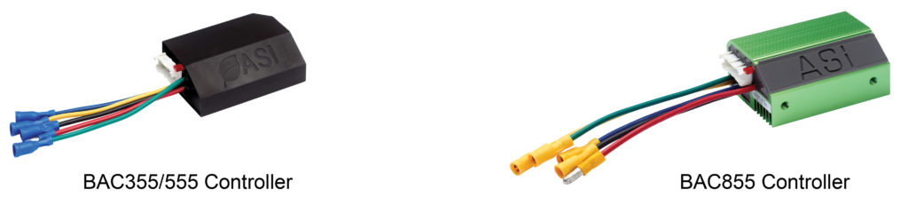
- Table 1 for eMobility controllers (BAC355, BAC555, BAC855).
- Table 2 for High power controllers (BAC2000, BAC4000, BAC8000).
- Table 3 for 2BTube
TIP – Brake 1/Analog input 2 and Brake 2/Analog input 3 are hybrid inputs. They are analog inputs but can be used as digital switches with High/Low trigger thresholds set in software.
WARNING – The communication ports are not surge protected like the other input ports. Voltage above digital Vmax will damage if not wipe out the communication board on the controller. Caution must be taken to prevent accidental short circuits to the communication ports, especially from battery positive.
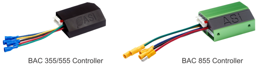
Table 1 – eMobility controller input specifications
| Type | QTY | Logic | Vin.min | Vin.max |
| Digital 5 V, pulled-up, active low – Halls | 3 | Vin.low Vin.high | – 2.5 V | 1.2 V – |
| Digital 5 V, pulled-up, active low – Peripherals | 2 | Vin.low Vin.high | – 4.6 V | 3.6 V – |
| 0-5 V analogue, configurable pull-up | 2 | Vin.high | – | 5.3 V |
| 0-5 V analogue, pulled-down | 1 | Vin.high | – | 5.3 V |
| 0-10 V analogue, pulled-down | 1 | Vin.high | – | 11 V |
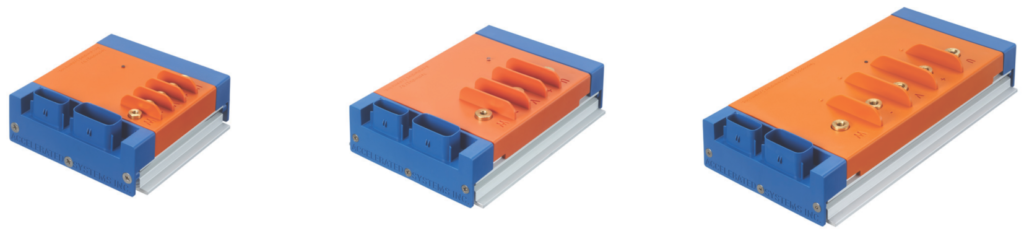
Table 2 – High power controller input specifications
| Type | QTY | Logic | Vin.min | Vin.max |
| Digital 5 V, pulled-up, active low – Halls | 3 | Vin.low Vin.high | – 2.5 V | 1.2 V – |
| Digital 5 V, pulled-up, active low – Peripherals | 2 | Vin.low Vin.high | – 4.6 V | 3.6 V – |
| 0-5 V analogue, configurable pull-up | 2 | Vin.high | – | 5.3 V |
| 0-5 V analogue, pulled-down | 1 | Vin.high | – | 5.3 V |
| 0-10 V analogue, pulled-down | 1 | Vin.high | – | 11 V |
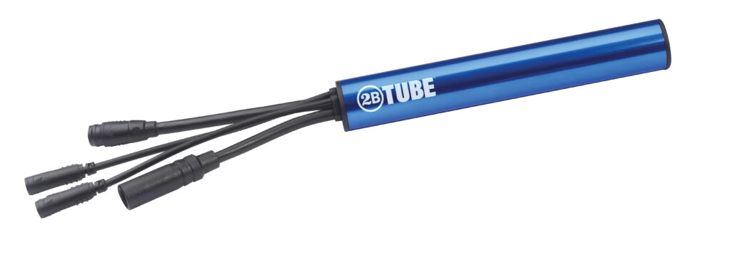
Table 3 – 2BTube controller input specifications
| Type | QTY | Logic | Vin.min | Vin.max |
| Digital 5 V – Halls | 3 | Logic Low Logic High | n/a 3.5 V | 0.5 V n/a |
| Digital 5 V – Peripherals | 2 | Logic Low Logic High | n/a 3.5 V | 0.5 V n/a |
| 0-5V Analogue | 3 | Vin.high | n/a | 5.3 V |
| 0-10 V analogue, pulled-down | 1 | Vin.high | n/a | 10.5 V |
Supported peripheral input types
Here is a list of peripherals, supported peripheral types and the preferred or required controller input pin.
Throttle:
- Hall 0-5V signal
- Any Analog input. Typically Throttle/Analog input 1 or ABMS/Analog input 4.
- Resistive 0-5V signal
- Any Analog input. Typically Throttle/Analog input 1 or ABMS/Analog input 4.
Pedal sensor:
- Single Hall, digital pedal cadence
- PFS/Digital input 2
- Single output dual Hall, digital pedal cadence
- PFS/Digital input 2
- Single Hall reverse, digital pedal cadence
- PFS/Digital input 2
- Quadrature speed, digital pedal cadence
- PFS/Digital input 2 (Sine) & Cruise/Digital input 1 (Cosine)
- Quadrature torque with digital pedal cadence
- Torque signal to any Analog input (Throttle/Analog input 1 only for v5.xxx), PFS/Digital input 2 (Sine) & Cruise/Digital input 1 (Cosine)
- Single Hall torque sensor
- Torque signal to any Analog input (only Throttle/Analog input 1 for v5.xxx), cadence to PFS/Digital input 2
- Single Hall reverse torque sensor
- Torque signal to any Analog input (only Throttle/Analog input 1 for v5.xxx), cadence to PFS/Digital input 2
Axle torque sensor:
- 0-5V Signal
- Any Analog input
Brake:
- Hall 0-5V signal
- Brake 1/Analog input 2, Brake 2/Analog input 3, PFS/Digital input 2 or Cruise/Digital input 1
- Resistive 0-5V signal
- Brake 1/Analog input 2 or Brake 2/Analog input 3
Display:
- Network
- Port 1 TTL-Rx and TTL-Tx
- or Port 2 CAN-L/LIN/TTL2-Rx and CAN-H/LIN/TTL2-Tx as applicable (depends on controllers specific communication protocol: CAN-BT, TTL-TTL, etc.)
- Depends on the controller’s specific communication protocol (CAN-BT, TTL-TTL, etc.), on the firmware version, and display protocol and version.
Battery management system, BMS:
- Analog State of Charge, SOC, (0-10V)
- Only ABMS/Analog input 4
- Network
- Port 1: TTL-Rx and TTL-Tx
- or Port 2: CAN-L/TTL2-Rx and CAN-H/TTL2-Tx as applicable
- Depends on the controller’s specific communication protocol (CAN-BT, TTL-TTL, etc.)
- Note: Other battery management models available in the software. Example: Voltage model
Motor temperature sensor:
- Thermistor type 0-5V signal
- Brake 2/Analog input 3 preferred or any analogue input
Wheel speed:
- Digital signal
- Hall A, to measure either the Hall or back electromotive force (back EMF)
- Cruise/Digital input 1 or Brake 2/Analog input 3 for external or internal speed sensors
Switches (walk mode, alternate power, alternate speed):
- Digital signal or ON/OFF switch
- Any Digital input
Peripheral input sources
| Name | Description | Units | Function | Throttle | Single/ Dual cadence sensor | Single Hall torque | Quadrature speed sensor | Quadrature torque sensor | Axle torque sensor | Cutoff brake | Regen brake | Display | BMS | Analog SOC | Motor temperature | Wheel speed | External switches | Address |
| Throttle | Analog input 1 | X | X | X | X | X | 270 | |||||||||||
| Analog bms soc | Analog input 4 | X | X | X | X | X | X | 275 | ||||||||||
| Brake 1 | Analog input 2 | X | X | X | X | X | X | X | X | 271 | ||||||||
| Brake 2 | Analog input 3 | X | X | X | X | X | X | X | X | X | X | 272 | ||||||
| Digital input | bit 2: Hall A | Hall A | X | 276bit2 | ||||||||||||||
| Digital input | bit 3: Pedal First input | PFS/ Digital input 2 | X | X | X | X | X | X | 276bit3 | |||||||||
| Digital input | bit 4: Cruise input | Cruise/ Digital input 1 | X | X | X | X | X | 276bit4 | ||||||||||
| network | UART, TTL, CAN, LIN, 485 | X | X | X | X | X | X | X | X |
Application configuration examples
Here are some input configuration examples:
Example 1: Throttle, brakes (single source for motor cutoff and regen) and pedal cadence sensor
- Throttle to Throttle/Analog input 1
- Brakes to Brake 1/Analog input 2
- Pedal cadence to PFS/Digital input 2
Example 2: Throttle, brakes, single Hall torque sensor, motor temperature and external wheel speed sensor
- Throttle to ABMS/Analog input 4
- Brake to Brake 1/Analog input 2
- Single Hall torque sensor cadence to PFS/Digital input 2 and Torque to Throttle/Analog input 1
- Motor temperature to Brake 2/Analog input 3
- Wheel speed to Cruise/Digital input 1
Pinout tables
eMobility controllers
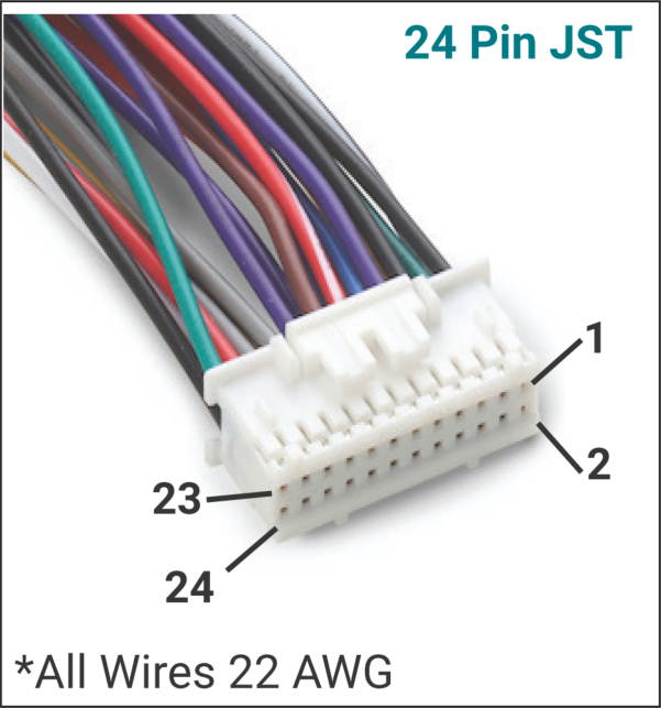
| Pin # | Classic Function | Function | Specifications |
| 1 | Hall GND | Hall GND | 20 mA max |
| 2 | Hall 5V | Hall 5V | 20 mA max |
| 3 | Hall A | Hall A | 0V ON, 5V OFF |
| 4 | Hall C | Hall C | 0V ON, 5V OFF |
| 5 | GND | GND | 400 mA max (shared with all GND’s) |
| 6 | Hall B | Hall B | 0V ON, 5V OFF |
| 7 | ABMS | Analog input 4 | 0-10V (pulled down) |
| 8 | Brake 2 | Analog input 3 | 0-5V (configurable pull-up/down) |
| 9 | PFS | Digital input 2 | Pulled up, active low |
| 10 | Brake 1 | Analog input 2 | 0-5V (configurable pull-up/down) |
| 11 | 5V output | 5V output | 50mA max |
| 12 | Cruise | Digital input 1 | Pulled up, active low |
| 13 | 12V output | 12V output | 90mA max |
| 14 | Throttle | Analog input 1 | 0-5V (pulled down) |
| 15 | HDQ | Low side switch | 100mA max |
| 16 | GND | GND | 400mA max (shared between all GND’s) |
| 17 | TTL-Rx | TTL-Rx | 5V TTL |
| 18 | TTL-Tx | TTL-Tx | 5V TTL |
| 19 | CAN-L (optionally TTL2-Rx or not used) | CAN-L (optionally TTL2-Rx or not used) | Depending on controller configuration: 120Ω termination resistor when configured for CAN or 5V TTL or pin not used |
| 20 | CAN-H (optionally TTL2-Tx or not used) | CAN-H (optionally TTL2-Tx or not used) | Depending on controller configuration: 120Ω termination resistor when configured for CAN or 5V TTL or pin not used |
| 21 | Key-out | B+ output | Always live connected to controller B+ |
| 22 | Key-in | Controller enable input | Requires B+, may draw up to 100mA |
| 23 | 6V Light | 6V switchable output | 500mA max |
| 24 | Light GND | Power GND | 500mA max (only for light) |
High power controllers
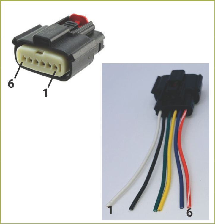
Table 6: High power 6-pin Molex MX150 connector pinout
| Pin # | Function | Current Limit | Transient Voltage Limit | Specifications |
| 1 | Hall 5V output | 100 mA | 47.5 V | |
| 2 | Hall GND | 100 mA | n/a | |
| 3 | Hall A | n/a | 90 V | Digital 5 V, pulled-up, active low |
| 4 | Hall B | n/a | 90 V | Digital 5 V, pulled-up, active low |
| 5 | Hall C | n/a | 90 V | Digital 5 V, pulled-up, active low |
| 6 | Analog input 3 | n/a | n/a | “Brake 2” or “Motor temperature sensor” 0-5V Analogue, configurable pull-up |
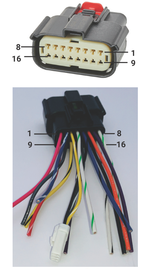
Table 7: High power 16-pin Molex MX150 connector pinout
| Pin # | Function | Current Limit | Transient Voltage Limit | Specification |
| 1 | Low side switch | 100 mA | 57 V | “HDQ” |
| 2 | Digital input 1 | n/a | 90 V | “Cruise” Digital 5 V, pulled-up, active low |
| 3 | TTL-Tx | n/a | 90 V | 5V TTL |
| 4 | 5V output | 50 mA | n/a | 50 mA Shared with all 5 V output, polyfuse protected |
| 5 | Digital input 2 | n/a | 90 V | “PFS” Digital 5 V, pulled-up, active low |
| 6 | Analog input 2 | n/a | n/a | “Brake 1” 0-5 V Analogue, configurable pull-up |
| 7 | Analog input 1 | n/a | n/a | “Throttle” 0-5 V analogue, pulled-down |
| 8 | 5V output | 50 mA | n/a | 50 mA Shared with all 5 V output, polyfuse protected |
| 9 | Key-in | Not limited | 90 V | Requires B+, may draw up to 100mA |
| 10 | CAN-L | n/a | > ±40V | 5 V, Software configurable 120 Ω termination resistor |
| 11 | CAN-H | n/a | > ±40V | 5 V, Software configurable 120 Ω termination resistor |
| 12 | Analog input 4 | n/a | n/a | “ABMS” 0-10 V analogue, pulled-down |
| 13 | TTL-Rx | n/a | 90 V | 5V TTL |
| 14 | Signal GND | 400 mA | n/a | 400 mA Shared with all Signal ground |
| 15 | Signal GND | 400 mA | n/a | 400 mA Shared with all Signal ground |
| 16 | 12V output | 50 mA | 47.5 V | Polyfuse protected |
2BTube controller (evaluation kit pin-out)
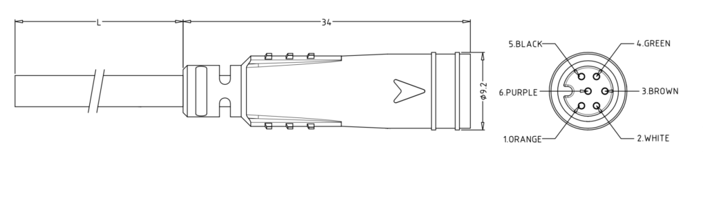
Table 8: 2BTube, Cusmade 0906 (signal-A), 6-pin female sensor signal pinout
| Pin # | Function (classic) | Function | Specifications |
| 1 | 5V output | 5V output | 50mA max |
| 2 | Cruise | Digital input 1 | Pulled up, active low |
| 3 | Throttle | Analog input 1 | 0-5V (pulled down) |
| 4 | Brake 1 | Analog input 2 | 0-5V (pulled up) |
| 5 | GND | GND | 100mA max (shared between all GND’s) |
| 6 | PFS | Digital input 2 | Pulled up, active low |
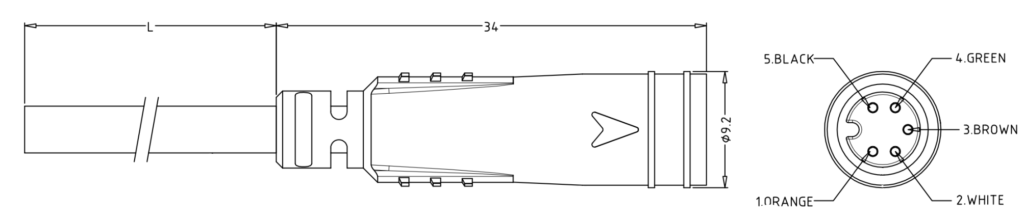
Table 9: 2BTube, Cusmade 0905 (signal-A), 5-pin female display signal pinout
| Pin # | Function (classic) | Function | Specifications |
| 1 | Key-out | B+ output | Always live connected to controller B+ |
| 2 | Key-in | Controller enable input | May draw up to 100mA |
| 3 | CAN-H | CAN-H | Configurable 120Ω termination resistor |
| 4 | CAN-L | CAN-L | Configurable 120Ω termination resistor |
| 5 | GND | GND | 100mA max (shared between all GND’s) |
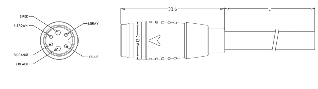
Table 10: 2BTube, Cusmade 1206, 6-pin male Battery pinout
| Pin # | Function (classic) | Function | Specifications |
| 1 | TTL-Tx | TTL-Tx | 5V TTL, 6V max |
| 2 | Battery – | Battery – | 19.5A max |
| 3 | CAN-H | CAN-H | Configurable 120Ω termination resistor |
| 4 | TTL-Rx | TTL-Rx | 5V TTL, 6V max |
| 5 | Battery + | Battery + | 19.5A max |
| 6 | CAN-L | CAN-L | Configurable 120Ω termination resistor |
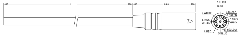
Table 11: 2BTube, Cusmade 1009, 9-pin female motor pinout
| Pin # | Function (classic) | Function | Specifications |
| 1 | Phase C | Phase C | 29A peak |
| 2 | Brake 2 | Analog input 3 | 0-5V (pulled up). Used for the temperature signal |
| 3 | Phase B | Phase B | 29A peak |
| 4 | Hall 5V output | Hall 5V output | 20mA max |
| 5 | Hall C | Hall C | 0V ON, 5V OFF |
| 6 | Hall B | Hall B | 0V ON, 5V OFF |
| 7 | Phase A | Phase A | 29A peak |
| 8 | Hall A | Hall A | 0V ON, 5V OFF |
| 9 | Hall GND | Hall GND | 20mA max |