Motor Sensorless Tuning
Introduction
During sensorless commutation start-up, the controller first injects current into one phase to align the motor to a known position. It then starts to increase the phase current frequency linearly until reaching the Sensorless closed loop enable frequency. At this point, there should be enough back EMF to determine the motor position and to lock into closed loop control. If not, it will try again, but this is a sign that it is not tuned correctly for the application.
In order for a motor to run in sensorless mode, the Motor position sensor type must be set to 2 sensorless. Note that, Motor discover mode 2 moving parameter discover is done in sensorless mode regardless of wheter the motor has Hall sensors or not.
This page outlines how to properly set up sensorless open loop start-up motor control. This process is iterative, it involves setting the sensorless parameters and running the motor under load in the application, not with the motor unloaded, to determine if motor startup response and feel are agreeable to the user.
It should be noted that for certain applications, sensorless motors are not recommended. For example, if the application requires that the motor be started under heavy load, a Hall sensored motor may be a better choice. Front-wheel drive bikes are also a better choice for sensorless commutation than rear-wheel drive systems.
Tuning
Motor startup response and feel is best adjusted by modifying Sensorless open loop starting current and the Sensorless closed loop enable frequency.
This diagram represents a motor phase current waveform to illustrate the function of each sensorless motor startup parameter.
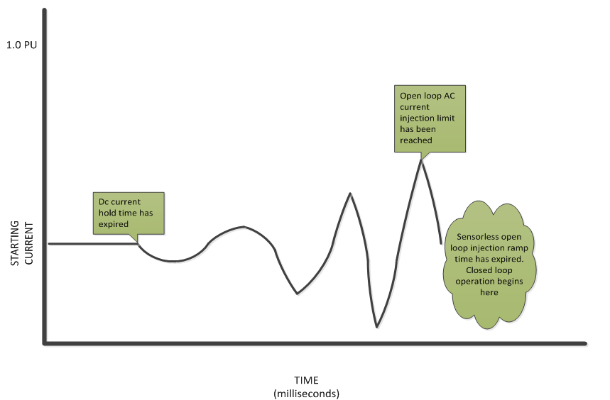
Sensorless open loop starting current: This is the amount of AC current relative to Rated motor current injected into the motor phases during the sensorless self-start. A higher current will force the motor to turn with more torque during the alignment and self-starting routines. So it’s common for this current to be pretty high, about 50% or more of the max phase current.
Sensorless open loop injection current ramp time: Duration of time it takes to reach Sensorless open loop starting current.
Sensorless open loop dc current hold time: This is the duration of time for which a DC current is injected into the motor in order to force the motor into a known position.
Sensorless open loop freq ramp time ms: This is the amount of time taken by the motor to spin from 0rpm to the Sensorless closed loop enable frequency. The shorter the time, then the quicker the motor is running closed-loop and the shorter the overall startup delay. However, it is important that the motor has enough time to get up to the Sensorless closed loop enable frequency with a loaded bike; if it tries to accelerate too quickly it may lose step with the magnets.
Sensorless closed loop enable frequency: This is the endpoint RPM of the sensorless start routine where the controller switches over to closed-loop regulation. It should be as low as possible while still producing enough back-emf voltage for stable closed-loop operation. Motors with higher RPM/V constants will usually need a correspondingly higher RPM for closed-loop control. Generally, approximately 10% of the motor rated electrical frequency is a good starting point.
Additional Information
Configuration Parameters
General sensorless tuning
| Name | Description | Units | Address |
| 106 | |||
| 107 | |||
| 108 | |||
| 109 | |||
| 110 |
Pedalec specific sensorless tuning
| Name | Description | Units | Address |
| 133 | |||
| 132 | |||
| 134 |
Additional information
| Name | Description | Units | Address |
| 330 |