Battery Foldbacks
Table of Contents
- Option 1- Voltage foldbacks
- Option 2 – SOC foldbacks
- Option 3 – Battery I2T Foldback
- Configuration parameters
Option 1 – Voltage foldbacks
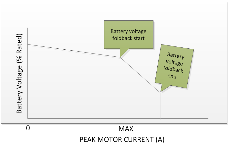
The controller can be configured to make use of the battery voltage provided by the controller to fold back the motor current limit to preserve long-term battery life. Folding back peak motor output current based on voltage prevents the battery from experiencing an excessive depth of discharge which can reduce the battery’s life cycle.
Battery current limiting based on battery voltage can be configured by setting the Low battery foldback end voltageand Low battery foldback starting voltage parameters. The battery voltage foldbacks are represented as a percentage of rated motor voltage. At the Low battery foldback starting voltage, the controller will foldback the peak motor current limit until the Low battery foldback end voltage value is reached at which point the motor current limit will be equal to the peak motor current value.
If using SOC foldbacks, set the voltage foldbacks out of range to prevent the voltage foldbacks competing with SOC foldbacks.

Option 2 – SOC foldbacks
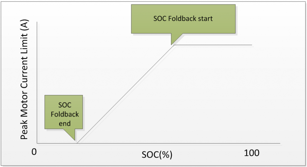
The BAC series of controllers can be configured to make use of the battery state of charge (SOC) information provided by the battery, or by the internal SOC calculator to fold back the motor current limit based on the SOC to preserve long-term battery life.
The SOC limiting of battery current can be configured by setting the Battery state of charge foldback end capacity and Battery state of charge foldback starting capacity parameters. The SOC foldbacks are represented as a percentage of SOC. At the Battery state of charge foldback starting capacity, the controller will foldback the peak motor current limit until the Battery state of charge foldback end capacity value is reached at which point the motor current limit will be set to zero.
If using voltage foldbacks, set the SOC foldbacks out of range to prevent the SOC foldbacks competing with voltage foldbacks.

Option 3 – Battery I2T foldback
Enable Motor features bit 3 Disable motor I^2t enable battery I^2t to calculate I2T based on battery current instead of motor current. This is useful when you have a motor temperature sensor handling foldbacks.
The battery current for calculating the respective percentages below is equal to Rated motor power divided by Rated system voltage.
For example, if your Rated motor power is equal to 960W and the Rated system voltage is 48V, your battery current “nameplate rating” for these calculations is 960W / 48V = 20A. If your continuous battery current is 15A, you would set Overload continuous current to 15A/20A = 75%.
Heating setup
If your battery current is between Overload continuous current and Overload heating current, you’ll have a gain between 0 and 1. Anything above Overload heating current, the gain is 1 on the overload accumulation heating formula. This is all relative to the Overload heating time. It will take Overload heating time at or above Overload heating current to reach 100% on the overload accumulator. If you are at the midpoint between the Overload continuous current and the Overload heating current, it will take twice as long to reach 100%.
You always start at 0% on the overload accumulator after restarting the controller; keep this in mind. For example, you trigger the overload warning, restarting the controller will clear it, and you might now overheat the motor/battery.
Cooling setup
If your battery current is between Overload continuous current and Overload cooling current, you’ll have a gain between 0 and 1. Anything below the Overload cooling current, the gain is 1 on the overload accumulation cooling formula. This is all relative to the Overload cooling time. It will take Overload cooling time at or below the Overload cooling current to reach 0% on the overload accumulator. If you are at the midpoint between the Overload continuous current and the Overload cooling current, it will take twice as long to reach 0%.
Foldbacks
Overload foldback start is when you want to start reducing battery current based on the overload accumulator value. Overload foldback end is when you want to cut all battery current based on the overload accumulator value. battery current reduction is linearly interpolated between start and end foldbacks.
Configuration parameters
Voltage foldback paramters
| Name | Description | Units | Address |
| 194 | |||
| 195 | |||
| 141 | |||
| 142 |
SOC foldback parameters
| Name | Description | Units | Address |
| 135 | |||
| 136 | |||
| 145 | |||
| 146 |
Battery I2T foldback parameters
| Name | Description | Units | Address |
| 99 | |||
| 100 | |||
| 101 | |||
| 102 | |||
| 103 | |||
| 104 | |||
| 105 | |||
| 127bit3 | |||
| 379 | |||
| 298 | |||
| 122 | |||
| 73 | |||
| 121 | |||
| 131 | |||
| 70 |
Foldback gains
If value less than 1, out is being actively folded back.
| Name | Description | Units | Address |
| 290 | |||
| 310 | |||
| 324 | |||
| 317 | |||
| 386 | |||
| 379 |
