Getting the motor spinning sensorlessly – eMobility
Table of Contents
- Introduction
- Warnings
- Tools required
- Required system information
- Wiring the controller
- Back-up your default parameter file
- Setting up the system voltage
- Configuring the motor profile
- Autotuning the motor
- Next steps
- Troubleshooting
1 – Introduction
On this page, we will set up your eMobility controller (BAC355, BAC555, and BAC855) to be able to control your motor sensorlessly. To do this we will be connecting your controller to power, your programming device and your motor.
These simple instructions are to show you how to get around the different Software, PC and Mobile BACDoor™.
2 – Warnings
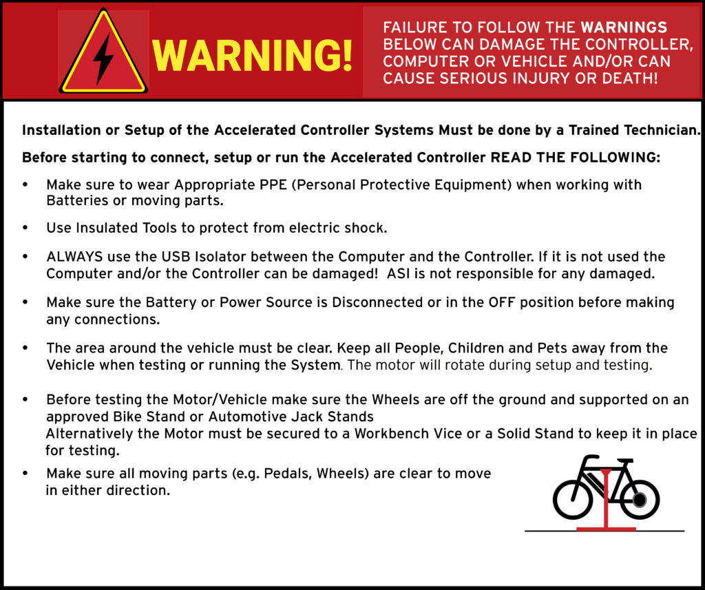
ATTENTION – Indicates a step or procedure required before proceeding to the next step or page.
CAUTION – Indicates a potentially hazardous situation which may result in minor injury or product damage.
WARNING – Indicates a Hazardous situation which if not avoided will result in serious injury/death to person(s) or damage to product and/or equipment.
TIP – Indicates a helpful Tip to make things easier and faster.
3 – Tools required
- Appropriate personal protective equipment (PPE) as required(e.g. Safety glasses, gloves, etc.)
- Standard mechanics tools (e.g. wrenches, screwdrivers)
- Vehicle stand, or motor stand to securely support the vehicle or motor drive wheel off the ground for testing (e.g. Bike stand, jack stands, etc.)
- Crimper for supplied Bullet Connectors
- TE Application Tooling 58433-3 or equivalent
- Crimper for JST Connectors (if required)
- JST Sales America Inc. WC-244 or equivalent
- ASI BACDoor software
4 – Required system information
Prior to installing your new controller, the following information will need to be gathered:
Table 1 – Required system information
| # | DETAIL | VALUE | WHERE TO FIND |
| 1 | Rated system voltage [V] | Battery OEM Specifications | |
| 2 | Rated motor current [A] | Motor OEM Specifications | |
| 3 | Rated motor speed [rpm] | Motor OEM Specifications | |
| 4 | Rated motor power [W] | Motor OEM Specifications | |
| 5 | Motor position sensor type? | Motor OEM Specifications (Hall based or Sensorless) | |
| 6 | # of Motor pole pairs | Motor OEM Specifications | |
| 7 | Motor output gear ratio | Motor OEM Specifications |
This information will be required to set up the motor and system profile in the BACDoor™ software. If you do not have these values, please contact your motor supplier to obtain this information.
The Rated system voltage is the nominal voltage of the battery in DC Volts.
The Rated motor current is the peak motor current on the sine wave (AC).
The Rated motor speed is the motor’s actual shaft speed. If geared, the OEM specification sheet may list the motors output speed only, this is not it. For example, a geared motor is rated as 400 rpm output, and the gear ratio is 3. The rated motor speed is the “motor speed” x Gear ratio; 400 rpm x 3 = 1200 rpm.
Rated motor power is the peak motor power. If only the nominal power is provided, this value may need to be inflated to account for losses, etc. For example, a motor rated to 250W may need to be entered as a 350W to get the 250W nominal power output.
TIP – Set your Rated motor power to rated system voltage multiplied by your batteries peak rated current output or lower to avoid damaging your battery or tripping your batteries BMS.
The Motor position sensor type is important should your motor be sensored, for example, hall based. If your motor is sensored, additional steps will be taken to set it up accordingly. See getting the motor spinning sensored. Note whether your motor is hall-based or sensorless.
The # of Motor pole pairs is equal to the number of magnets in the motor divided by 2. These are called pole pairs. See the troubleshooting section below for how to count motor pole pairs if this value is not available on your motor datasheet.
The Motor output gear ratio is the motors internal gear ratio. If the motor is direct drive, enter 1 since there are no gears. If the motor is geared hub motor, enter the gear ratio of the motor. If the motor is mid-drive, enter the gear ratio before the final drive just like a normal motor.
5 – Wiring the controller
This section will walk you through the basic wiring required to get your bike up and running with the ASI Controller. It will allow you to get the Motor spinning to confirm functionality and become familiar with the Controller and BACDoor™.
WARNING – Integrating your controller into your electrical system requires a functioning Battery management system (BMS), an appropriately sized Fuse, appropriate Wire gauge, a Precharge switch (or equivalent) and a Safety cutoff switch are required for the safe operation of the controller. Not using these components poses a serious safety risk, permanent damage to the controller and other components in the case of an issue. Anti-spark connectors are recommended.
CAUTION – Voltage and current spikes must not exceed input or output ratings.
CAUTION – The controller is only designed for use with battery-powered electrical systems.
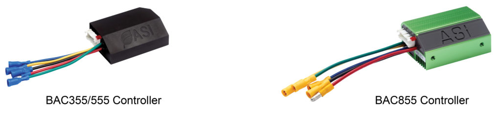
Table 2 – Controller Power & Motor Wiring Table
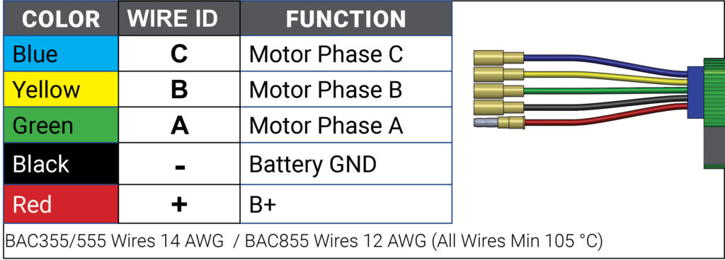
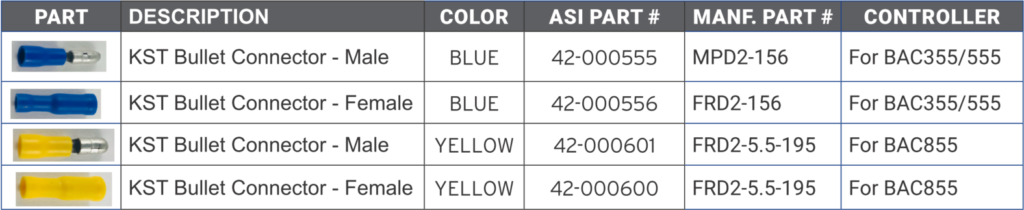
Table 3 – Required components
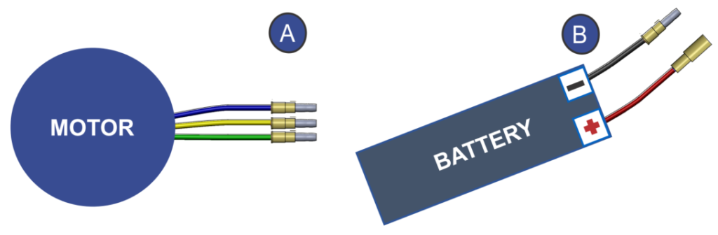
5.1 Wire crimping
A. Attach and crimp the supplied KST Bullet Connectors to the 3 Phase Wires from the Motor.
B. Attach and crimp the supplied KST Bullet Connectors to the Battery Positive and Negative Wires. Note that the Battery Positive wire on the controller side is male.
ATTENTION
- The Red (Battery +) Wire on the Controller is a male Connector, be sure to use the female Connector supplied on the Battery + Wire.
- Make sure to use the correct size of KST Bullet Connectors (see Table 3).
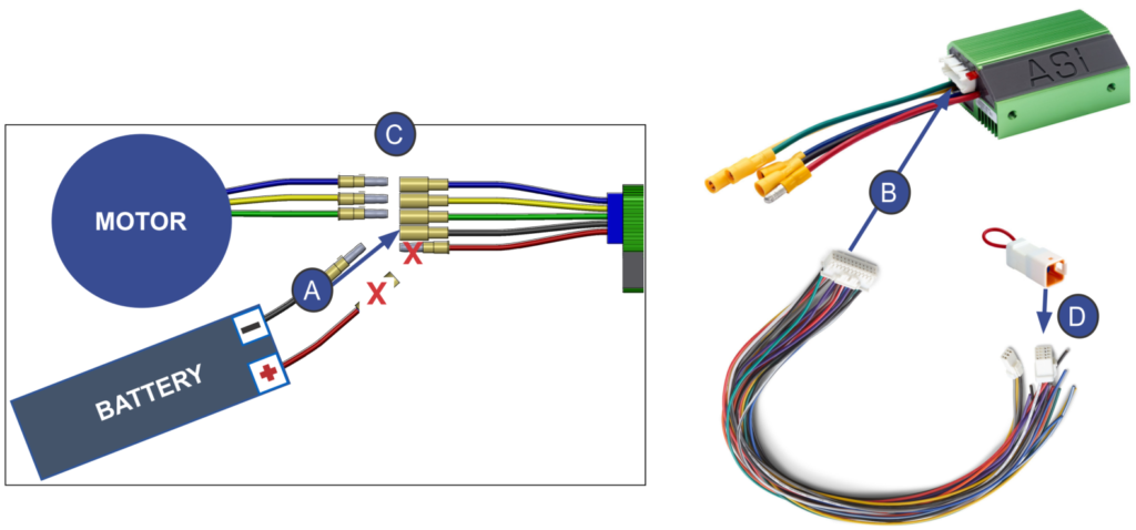
5.2 Required components wire connections
A. Plug-in the Black (Battery -) from the Controller to the negative from the Battery to ground the system.
B. Next, plug the Evaluation Harness to the 24pin Connector on the Controller
C. Plug the 3 phase Cables from the Controller to the appropriate phase wires coming from your Motor.
D. Plug the Evaluation Key Connector Switch into the 6-pin Connector on the Evaluation Harness.
CAUTION – DO NOT connect the Red + Cable until after the Computer Set Up steps on the next page!
CAUTION – ALWAYS use the USB Isolator between the Computer and the Controller. If it is not used the Computer and/or the Controller may be damaged! ASI is not responsible for any damaged.
5.3 Computer setup
A. Plug the USB to TTL Cable into the 3-pin Connector on the Evaluation Harness.
B. Plug the other end of the USB-TTL Cable to the USB Isolator.
C. Plug the USB Isolator Cable into the USB Isolator
D. Plug the USB Cable into the Computer.
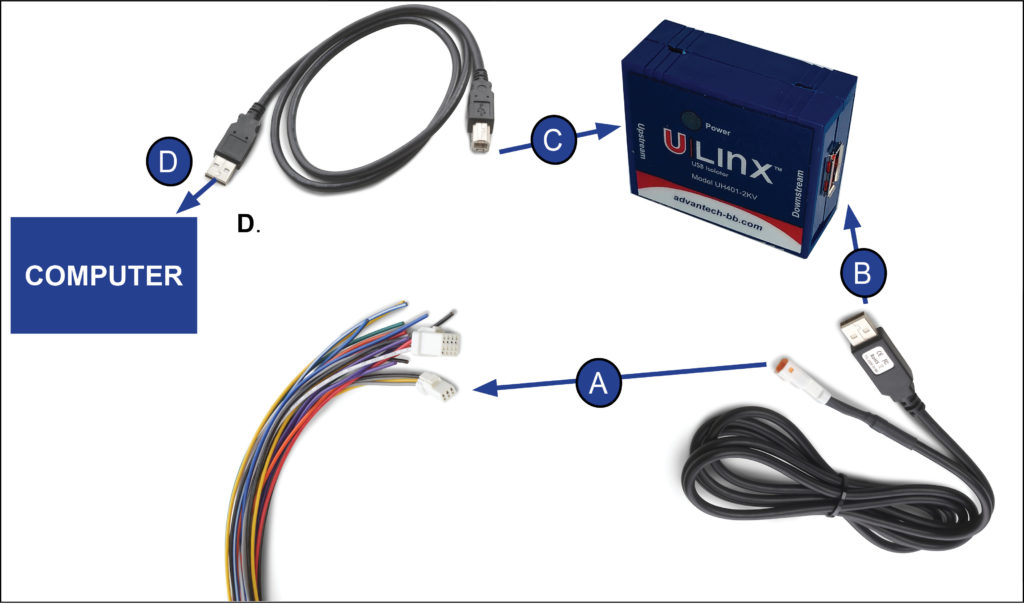
E. Allow your Computer to install the appropriate Drivers.
F. Now Plug the Red (Battery +) wire from the Controller into the Positive cable from the Battery. If the Battery does not have an off switch, you may notice a minor spark when this connection is made, this is normal. If the Battery has a Power Switch, turn it to the ON position.
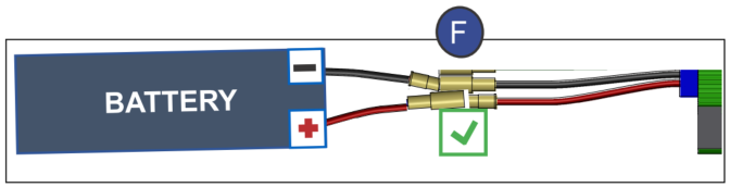
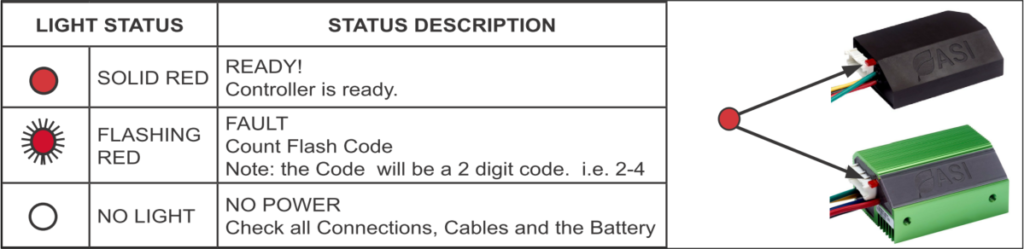
Note: The Red LED Status Light should now be visible on the controller.
Table 4
6 – Back-up your default parameter file
See using BACDoor Mobile or using BACDoor PC if you have not already familiarized yourself with our software.
Connect to your controller now. In PC BACDoor™ the Tx & Rx lights should be continuously flashing. In BACDoor™ Mobile, the green light, top left of the app, should be flashing continuously. If it is not connecting, see the troubleshooting section below.
Attention – Before proceeding with the setup backup the original Parameter File on the Computer. This is important should you need to recover the controller to a known state.
Option A) BACDoor™ PC
With the controller connected, select Save to File (512) from the Parameter dropdown menu to save your controllers parameters to file.
Option B) BACDoor™ Mobile
In BACDoor™ Mobile, with the controller connected, select Menu from the Channels page, then select Save to file, enter a name and save it to your app directory to recover from it later.
7 – Setting up the system voltage
TIP – Hover over the information icon for parameter location in BACDoor™ shorthand.
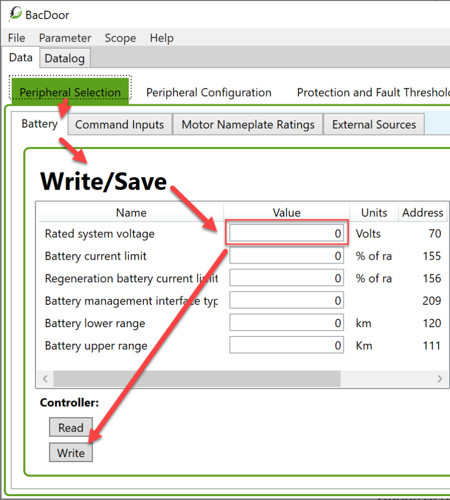
Once you have established communication between your Controller and BACDoor™, we can now begin setting up the system. The first step is to enter the Rate System Voltage you found for Table 1 above. Here we enter the batteries nominal voltage, e.g. 36V, 48V, 72V, etc. and not the full or dead battery voltage, e.g. 40V and 51.2V for a 48V nominal battery for example.
Option A) BACDoor™ PC
Navigate to the Peripheral Selection tab, select the Battery page. In the Write/Save section, enter your battery nominal voltage value for Rated System Voltage . Press <Enter> on your keyboard after each parameter entry, or the Write button below the Write/Save section after every entry has been entered to save them to the controller temporarily. Then select Save to Flash from the Parameter drop-down menu to save it permanently.
Attention – Only Save to Flash saves parameter entries permanently to the controller. <Enter> and Write only write until the controller power is cycled.
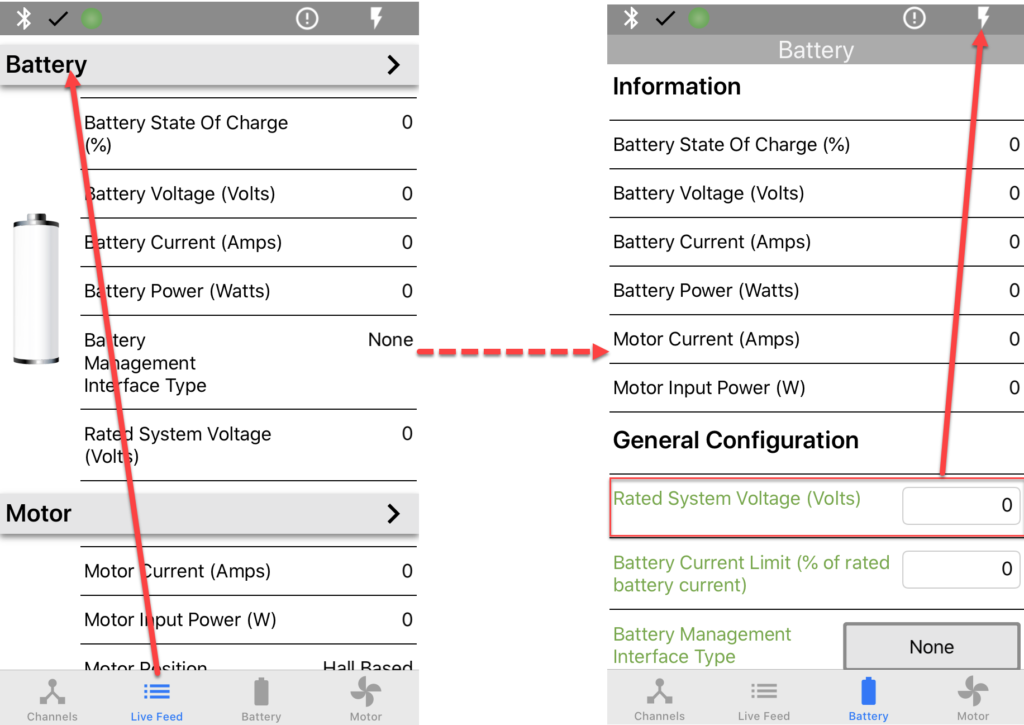
Option B) BACDoor™ Mobile
Navigate to the Live Feed tab, select the Battery page. In General Configuration, enter your battery nominal voltage value for Rated System Voltage in the adjacent box. Once the value is entered, it is temporarily written to the controller. After entering the value, select the Lightning bolt icon in the top right of the app to save the parameters to flash.
Attention – Only pressing the Lightning bolt icon saves parameter entries permanently to the controller. Parameter entries are otherwise only written until the controller power is cycled.
Now that the battery voltage is set, any warnings that may have been there should have cleared.
8 – Configuring the motor profile
Here we will enter the base motor parameters that we found for Table 1 above.
Option A) BACDoor™ PC
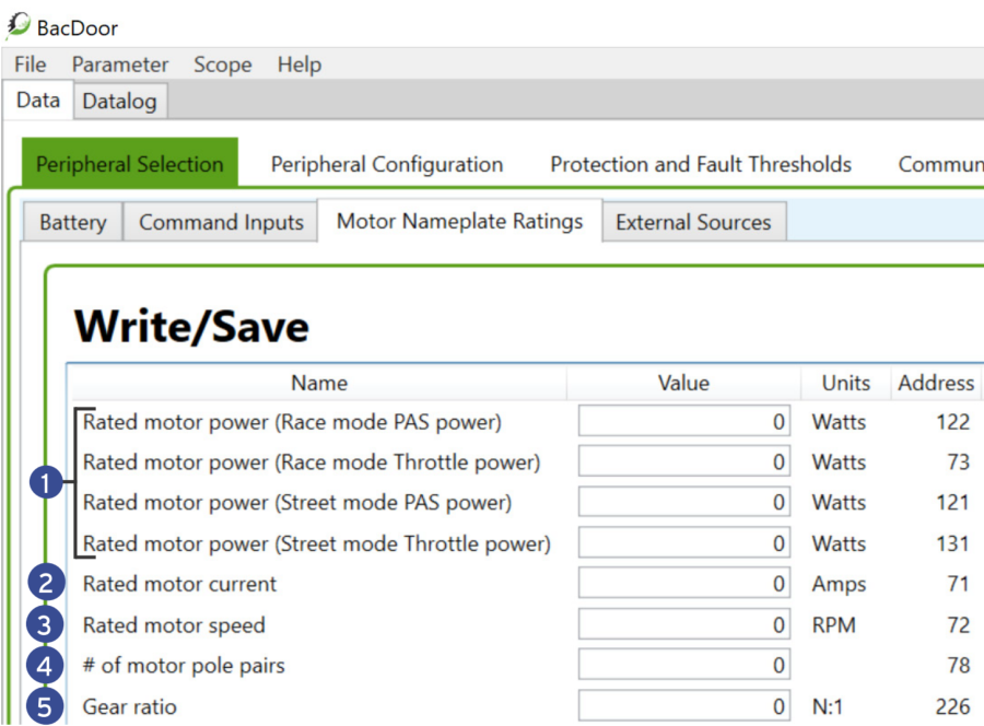
Navigate to the Peripheral Selection tab, select the Motor Nameplate Ratings page. In the Write/Save section,
(1) enter the Rated motor power in all four variants of this parameter listed in the image below,
(2) enter the Rated motor current ,
(3) enter the Rated motor speed ,
(4) enter the # of motor pole pairs ,
and (5) enter the Gear ratio .
Press <Enter> after every entry or press Write below this section after entering each parameter. Add any parameters if missing as necessary. See the image below for reference. Press Save to flash in the Parameter drop-down menu.
Option B) BACDoor™ Mobile
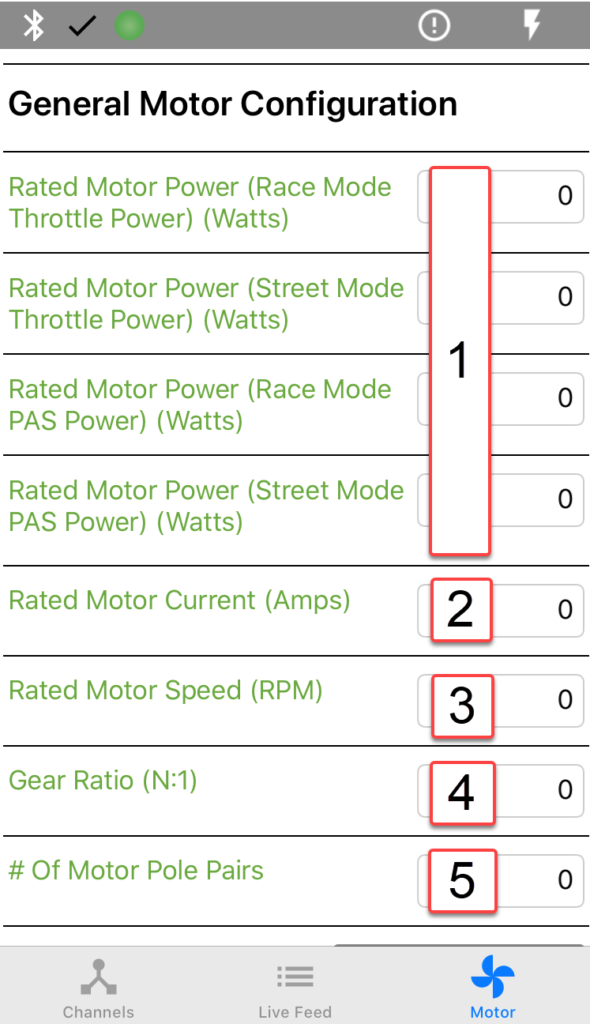
Navigate to the Live Feed tab, select the Motor page. In the General Motor Configuration section,
(1) enter the Rated Motor Power in all four variants of this parameter listed in the image below,
(2) enter the Rated Motor Current ,
(3) enter the Rated Motor Speed ,
(4) enter the # of Motor Pole Pairs ,
and (5) enter the Gear Ratio .
Add any parameters if missing as necessary. See the image below for reference. Press the Lightning bolt to Save to flash.
9 – Autotuning the motor
In this section, we will use the controller to discover the motor’s resistance (Rs) and inductance (Ls) values. Then we’ll verify the motors rated rpm.
WARNING
- The Motor will be spinning in the next steps for up to 20 seconds at 50% of the Rated motor speed (RPM) and high current.
- Make sure all moving parts (e.g. Motor, Pedals, Wheels, etc.) are clear to move in either direction.
- Make sure the motor is securely mounted and the wheels are off the ground.
To stop the motor
- In PC BACDoor™, enter 0 for Motor discovery.
- Or turn off the controller,
- As a last resort, disconnect the battery. This has a high chance of damaging the controller permanently.
CAUTION – Make sure the system is connected to an adequate power source. This test will draw the full rated motor current and can damage the power source if it is inadequate.
TIP – Make a backup copy of the parameter file often by saving it to file as shown before. It can be sent to ASI for support or you can revert if strange behaviour occurs.
Option A) PC BACDoor™
First, we will measure the motors inductance (Ls) and resistance (Rs) via a feature called Motor discover mode. This test will make the motor possibly index to the nearest correct motor pole pair and the motor will make a high pitch hum or squeal.
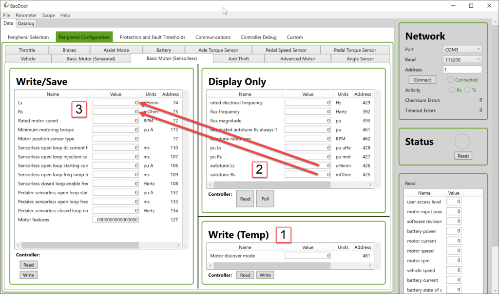
(1) Navigate to the Peripheral Configuration tab, select the Basic Motor (Sensorless) page. In the Write (Temp) section, enter 1 in the parameter Motor discover mode value field, and press <Enter> or Write. The motor will now index slightly and make a noise as described above.
(2) After the motor has finished making noise (2 to 3 seconds). In the Display (Only) section, press Read. The populated autotune Ls and autotune Rs values should both be positive.
(3) Copy the autotune Ls value from the Display (Only) section to Ls in the Write/Save section. Copy the autotune Rs value from the Display (Only) section to Rs in the Write/Save section. Click the Write button in the Write/Save Section. Save to flash via the Parameter drop-down menu.
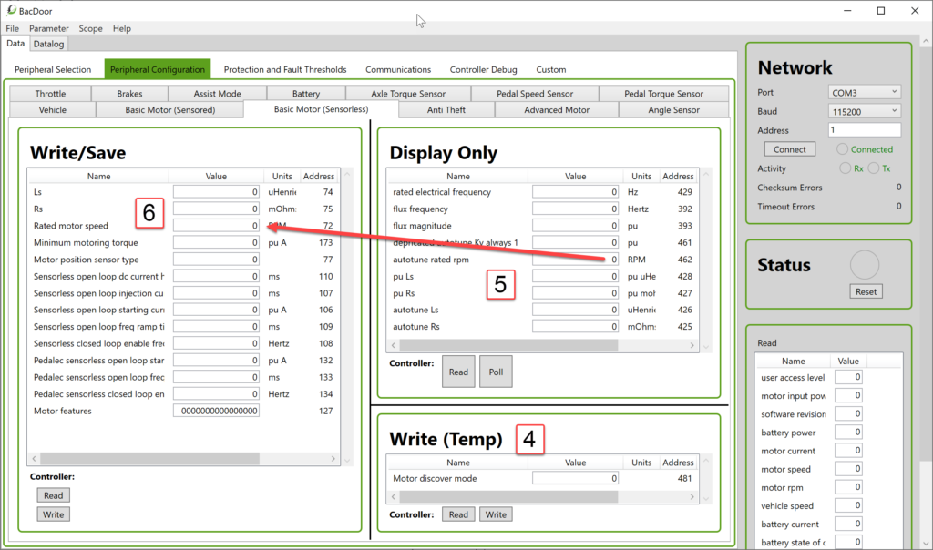
Now we will autotune the rpm of the motor. This test will spin the motor for about 20-30 seconds and at about half the rated motor speed.
(4) In the Write (Temp) section, enter value 2 in Motor discover mode , and press <Enter> or click Write. The motor will now spin for about 20 seconds. The motor should spin up to half of the motors rated speed that we entered earlier and run at this speed steadily. The motor should run in the expected/correct “forward” direction. Should an issue arise, to stop the test, you can enter 0 in the Motor discover mode or disconnect the power to the controller or unplug the key. If not see the troubleshooting section below.
(5) Once the motor has stopped spinning, press Read in the Display Only section. The autotune rated rpm value should be near enough to the value you entered in the Rated motor speed previously, if not see the troubleshooting section below.
(6) Copy the autotune rated rpm value to the Rated motor speed in the Write/Save section and press <Enter>. Save to flash via the Parameter drop-down menu.
Option B) BACDoor™ Mobile
This will be much quicker than with PC BACDoor™. First, we will measure the motors inductance (Ls) and resistance (Rs) via Motor Setup. This test will make the motor possibly index to the nearest correct motor pole pair and the motor will make a high pitch hum or squeal.
(1) From the Live Feed tab, select the Motor page. In the Motor Setup section, press Run under Analyze Motor Resistance (Rs) and Inductance (Ls) . The motor will now index slightly and make a noise as described above.
(2) After the motor has finished making noise (2 to 3 seconds). Verify that both the values listed in Accept measured Rs and Ls are positive. If so, press copy to save the values automatically to Rs and Ls parameters.
(3) Save to flash via the Lightning bolt button.
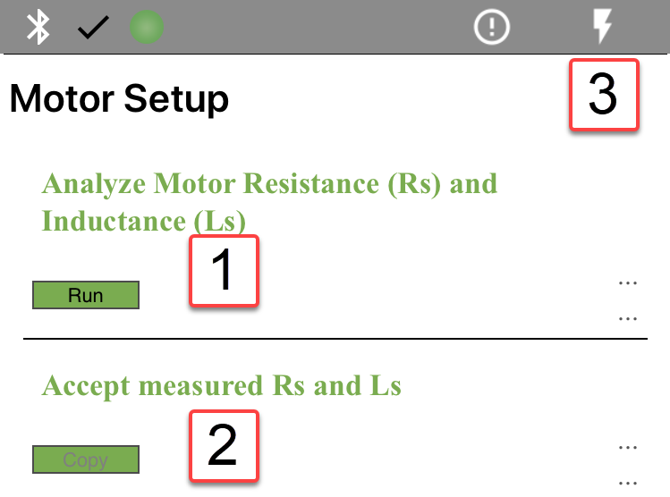
Now we will autotune the rpm of the motor. This test will spin the motor for about 20-30 seconds and at about half the rated motor speed.
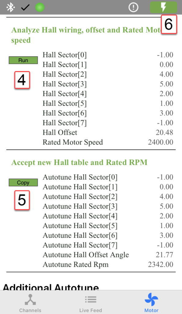
(4) In the Motor Setup section, press Run below Analyze Hall wiring, offset and Rated Motor speed . The motor will now spin for about 20 seconds. The motor should spin up to half of the motors rated speed that we entered earlier and run at this speed steadily. The motor should run in the expected/correct “forward” direction. Should an issue arise, to stop the test you must disconnect the power to the controller or unplug the key. If not, see the troubleshooting section below.
(5) Once the motor has stopped spinning, verify the rated rpm that populated in the Accept new Hall table and Rated RPM is near enough to the value you entered as the Motor rated speed . If not see the troubleshooting section below. If so, press copy to save the autotune rated motor speed automatically to the Motor Rated Speed parameter.
(6) Save to flash via the Lightning bolt button.
10 – Next steps
Proceed to Hall sensor setup if your motor has halls, if not proceed to set up your peripherals by going to Hardware Inputs.
11 – Troubleshooting
TIP – Hover over the status light in PC BACDoor™ or go to Live Feed and scroll to the top to Faults and Warnings to see the details of faults or warnings.
11.1 – Connection/communication issues
Assuming the controller is powered on (solid or blinking light on the controller). Try the following:
PC BACDoor™:
- Remove all peripherals connected to the controller (e.g. displays, throttle, etc.), if any. Ensure the controller is powered on (connected to the battery), the LED should be lit. Ideally solid, or possibly it is flashing a code sequence.
- If the controller LED is not solid, see the Faults and warnings troubleshooting for more information.
- Remove all peripherals other than the basics from your computer to isolate which Port the controller is connected to.
- Ensure the Network Baud rate in BACDoor™ is set to 115200, our default value. If not, try 9600, as the Baud rate value on the controller may have been affected.
- Once connected set Baud rate and Baud rate port2 set to 115200. Save to flash, and then power cycle the controller. Set the Network Baud Rate to 115200 now, and try to reconnect.
BACDoor™ mobile:
- Does the part number description have BlueTooth(BT)? (e.g. TTL-BT or CAN-BT)
- Verify Bluetooth is ON on your device.
- Verify you are attempting to connect to the correct device, generally it is “e-Bike”. Placing the phone as close as possible to the controller and refreshing the Channel page helps identify the correct controller to connect to as it should have the highest strength %.
- Disconnect any peripherals if any are connected, e.g. Displays.
11.2 – Counting motor pole pairs
Contact ASI support.
11.3 – Ls and/or Rs are negative
If you get negative values, the problem may be the wiring or it may be internal to the motor. Possible causes include:
- The battery does not supply sufficient current for the test. Try lowering your Rated motor current and try again. Location:
- Lower Rated motor current
- For mobile, lower Rated Motor Current
- There may be insufficient current, try increasing Rated motor current.
- The Rated motor rpm may be set too high, try lowering it.
- Verify your phase wires are not shorting anywhere. This may be internal to the motor.
- Two or more phases may be shorted together. Verify your phases haven’t shorted together, as above it may be an internal issue.
- A phase may be unplugged.
11.4 – The motor/wheel does not spin
- The controller may have faulted, check the controller faults or check if the controller LED is flashing and record this value. See the Faults and warnings troubleshooting for more information.
- The motor may have loose phase wires, verify all connections.
- If it is a freewheeling motor, the motor may be spinning backwards and thus not engaging. Correct this by swapping the phases as explained in 10.3 below.
- Your brakes may be enabled and enabling motor cutoff. Verify if eBike flags bits 0 (Brake) and 1 (cut-out) are 1 (enabled). If they are both enabled, your brakes are enabled and it is cutting off the motor current. If only the cut-out is enabled, something else is cutting current to the motor. Verify you have no peripherals connected, and possibly restart from your previously saved default parameter file.
- digital eBike flags: bits 0 & 1 , click poll to see the live flag values.
- Or for Mobile, Ebike Flags enabled bits appear in the right column, disabled bits do not.
- Rated motor power or Rated motor current set too low to overcome the initially required motor torque to spin.
- Correct/increase Rated motor current and Rated motor power (all 4 motor power values)
- For mobile, correct/increase Rated Motor Current and Rated Motor Power (all 4 motor power values)
- Try setting the Sensorless closed loop enable frequency to 10% of the rated electrical frequency.
- Set Sensorless closed loop enable frequency to 10% of rated electrical frequency (click read to see value)
- For mobile, set Sensorless Closed Loop Enable Frequency to 10% of Rated Electrical Frequency
- EN controllers expect some form of pedal input per legislation.
11.5 – The motor spins in the wrong direction
If your motor is spinning in reverse, the most likely cause is the phase wiring. Whether internally in the motor, or your connection to the controller. You can swap the phases physically (option 1) or in the controller digitally (option 2).
- Option 1 – Physically swap phase wires A (Green) and C (Blue)
- Option 2 – In BACDoor™, enable Motor features bit 0.
- For PC BACDoor™, set Motor features: Bit 0 to 1,
- or for BACDoor™ Mobile, enable Bit 0 Swap phase A and phase C .
11.6 – The motor does not spin as quickly as expected
- If the actual motor speed appears too slow. Check your motor nameplate ratings; if the Rated motor speed is an estimate and the motor is running stably at a constant speed during analysis, use the autotune Rated rpm value as the Rated Motor speed.
- In 6.016 and higher firmwares, motor discovery occurs at ~20% of the calculated motor electrical frequency. Previously it was ~50%.
- If the indicated or autotune Rated rpm is wildly off, verify your # of motor pole pairs is set correctly.
- Correct # of motor pole pairs
- For mobile, correct # Of Motor Pole Pairs
- Try setting the Sensorless closed loop enable frequency to 10% of the rated electrical frequency.
- Set Sensorless closed loop enable frequency to 10% of rated electrical frequency (click read to see value)
- For mobile, set Sensorless Closed Loop Enable Frequency to 10% of Rated Electrical Frequency
11.7 – The motor speed is unsteady during the rated motor speed analysis
- A phase wire could be disconnected
- Rated motor speed may be set too far from the correct value. Double or halve the Rated motor speed parameter value, then use the motor discovery again to analyze the motor speed.
- Verify your pole pairs are correct. See 11.2 above if you need to manually count the pole pairs. To change the value:
- # of motor pole pairs
- Or for Mobile, # Of Motor Pole Pairs
- Try setting the Sensorless closed loop enable frequency to 10% of the rated electrical frequency.
- Set Sensorless closed loop enable frequency to 10% of rated electrical frequency (click read to see value)
- For mobile, set Sensorless Closed Loop Enable Frequency to 10% of Rated Electrical Frequency
11.8 – Hall vs Sensorless position Fault
Your Motor position sensor type is set to 0 (Hall based) or 1 (Hall start and sensorless run) and it is throwing an error as a result. Set this value to 2 (sensorless) for the motor speed autotune.
- Set Motor position sensor type to 2
- Or for mobile set Motor Position Sensor Type to Sensorless.
11.9 – I tried all the above and I still need help!
If after the above troubleshooting it still does not function correctly, please contact send us an email at support@acceleratedsystems.com, with your parameter file and a description of your issue.