Display
Table of contents
- Introduction
- Warnings
- Required tools
- Supported display types
- Display wiring
- Display setup
- Configuration parameters
- Troubleshooting
1 – Introduction
This section will guide you through setting up your display.
2 – Warnings
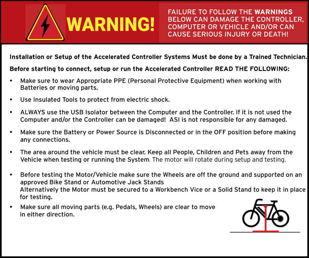
ATTENTION – Indicates a step or procedure required before proceeding to the next step or page.
CAUTION – Indicates a potentially hazardous situation which may result in minor injury or product damage.
WARNING – Indicates a Hazardous situation which if not avoided will result in serious injury/death to person(s) or damage to product and/or equipment.
TIP – Indicates a helpful Tip to make things easier and faster.
3 – Required tools
- Appropriate personal protective equipment (PPE) as required(e.g. Safety glasses, gloves, etc.)
- ASI BACDoor software
- 22 AWG Wire strippers (eMobility)
- 18 AWG Wire strippers (high power)
- Vehicle stand, or motor stand to securely support the vehicle or motor drive wheel off the ground for testing (e.g. Bike stand, jack stands, etc.)
4 – Supported display types
- Modbus & CAN displays
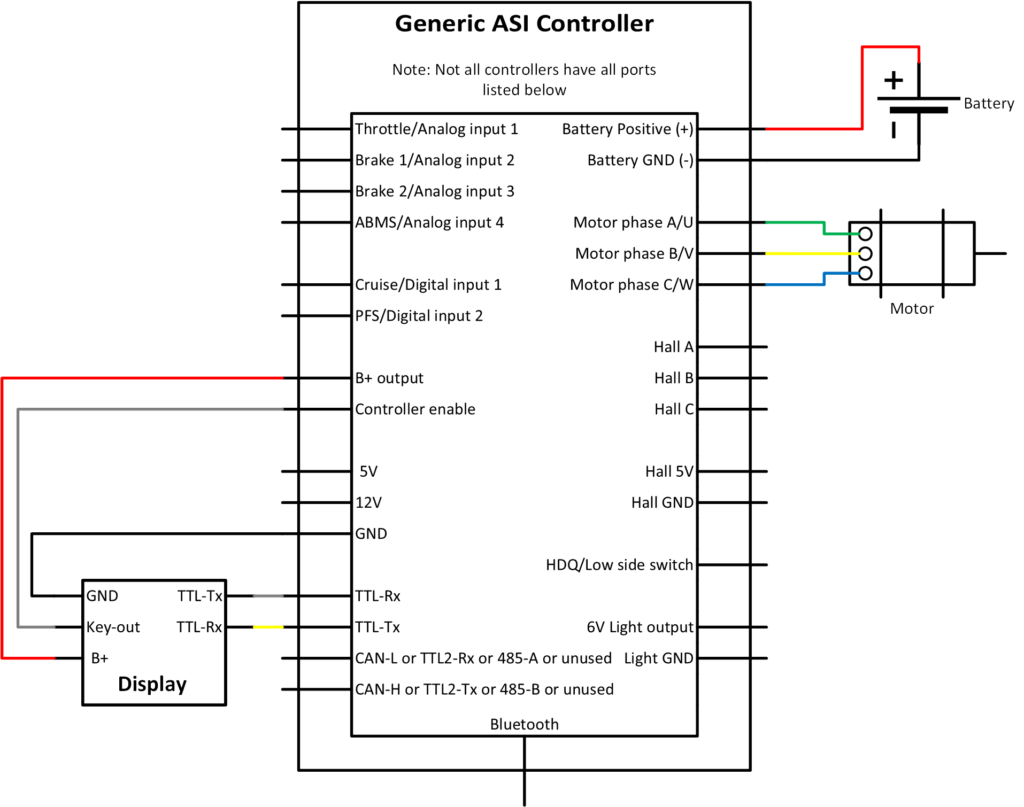
5 – Display wiring
WARNING – Extreme care must be taken when wiring and connecting displays to the controller. Displays generally use 5 wires. One of these wires carry battery voltage to the display, and another from the display. If wired incorrectly, battery voltage could be applied to either communication pins, or shorted to ground. The result being at best a blown communication port and at worst a blown control board from drawing excessive current through it.
WARNING – If you are unsure of the pinout of the display or the controller, do not connect them together. Contact your display manufacturer to confirm the display wiring pinout and verify it against how you have wired it to the controller.
TIP – Make sure you verify continuity through the plug. When looking at the plug faces, the male pinout should mirror the female pinout.
Displays can be connected to either:
- Port 1 TTL-Rx and TTL-Tx
- or Port 2 CAN-L/LIN/TTL2-Rx and CAN-H/LIN/TTL2-Tx as applicable
- depends on controllers specific communication protocol (CAN-BT, TTL-TTL, etc.), and on the firmware version, display protocol and version
Typical display wiring where the display is used to turn on the controller (Example: APT 750C 72V version, or EggRider connected to a system that peaks at 60V or less.)
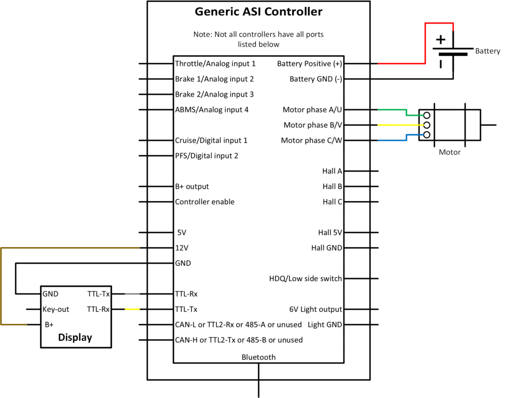
Typical display wiring, where an external switch is used to turn the controller ON/OFF. Example: Eggrider connected to 12V supply because the system voltage is above 60V.
6 – Display setup
WARNING – Ensure vehicle is secured in-case the motor engages unexpectedly while manually configuring your display.
TIP – Hover over the information icon for parameter location in BACDoor™ shorthand.
TIP – Make a backup copy of the parameter file often by saving it to file as shown before. It can be sent to ASI for support or you can revert if strange behaviour occurs.
With the display connected to the controller
- Enable Communications configuration vector bit 10 Enable Ebike.
- Set the Display protocol if using port 1 and Display protocol2 if using port 2 to your displays communication protocol.
- Set your Assist mode source to display.
- Set your Walk mode signal source to display.
- Enable Features bit 11 Walk mode enable.
- Set your Wheel diameter in mm.
- Set your Wheel speed sensor source & Wheel speed sensor pulses per revolution.
Further information regarding assist mode setup is available here: Assist level configuration.
7 – Configuration parameters
General configuration
| Name | Description | Units | Address |
| Display protocol | 66 | ||
| Walk mode signal source | 138 | ||
| Features | Walk mode enable | 212bit11 | |
| Features | Boost mode enable | 212bit12 | |
| Battery upper range | 111 | ||
| Battery lower range | 120 | ||
| Display language and units | 112 | ||
| Wheel diameter | 227 | ||
| Wheel speed sensor source | 193 | ||
| Wheel speed sensor pulses per revolution | 231 |
I/O Features
| Name | Description | Units | Address |
| Features2 | Headlight Always ON enable | 174bit0 | |
| Features2 | HDQ Replicating HALL | 174bit1 |
Trip Information
| Name | Description | Units | Address |
| Trip meter | 408 | ||
| Wheel pulse counter | 407 | ||
| LIN odometer | 404 | ||
| LIN trip | 405 | ||
| LIN average trip velocity | 406 |
Wheel Speed Setup and Verification
| Name | Description | Units | Address |
| warnings | Wheel Speed Sensor(flash code 5,4) | 277bit3 | |
| measured wheel RPM | 313 | ||
| wheel RPM (motor based) | 312 | ||
| wheel RPM (speed sensor based) | 311 |