Motor Temperature
Table of Contents
- Introduction
- Motor temperature sensor input & wiring
- Motor temperature sensor setup
- Brake1 or 2 to Hall Ground formula
- Testing the temperature feedback
- Configuration parameters
Introduction
Temperature sensors in motors are the ideal way to monitor the motor’s health and avoid over-temperature damage to the motor and its components. This page will guide you to set up your motor temperature sensor.
Motor temperature sensor input & wiring
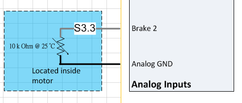
Typically, a thermistor is wired as shown in the figure below with one end connected to the Brake 2/Analog input 3 or Brake 1/Analog input 2 and the other being connected to the ground.
Throttle/Analog input 1 and ABMS/Analog input 4 are also valid input options.
Motor temperature sensor setup
- Enable Features bit 5 Motor temp sensor enable.
- Select the Motor temperature source.
- Enter the motor temperature sensor voltage for each of the following:
- Temperature feedback V at 0 C
- Temperature feedback V at 25 C
- Temperature feedback V at 50 C
- Temperature feedback V at 75 C
- Temperature feedback V at 100 C
- Temperature feedback V at 125 C
The calculator below can be used to estimate the motor temperature sensor voltage for each temperature. This calculator assumes the sensor is connected to Brake 1/Analog input 2 or Brake 2/Analog input 3 and ground as shown above, and the inputs are pulled up. If tied to Hall Ground with motor Hall position sensors, see the formula below.
On 6.xxx firmware and up, Brake 1/Analog input 2 or Brake 2/Analog input 3 must be pulled up: Features2 bit 6 Brake 1 Pullup enable, and Features2 bit 7 Brake 2 Pullup enable, respectively.
Contact support@acceleratedsystems.com with your temperature sensor datasheet if you need to estimate the values for AMBS or Throttle inputs.
Motor thermistor voltage calculator
| Temperature | Resistance | Calculated internal sensor voltage |
|---|---|---|
| 0° | ||
| 25° | ||
| 50° | ||
| 75° | ||
| 100° | ||
| 125° |
Input Linearity Graph
Note: The temperatures outside of 0 °C through 125 °C are linearly extrapolated for temperatures above 125 °C and below 0 °C.
Brake1 or 2 to Hall Ground formula
If tying the sensor from Brake 1/Analog input 2 or Brake 2/Analog input 3 to Hall ground, on a motor with Hall position sensors, this formula can be used to better estimate the motor temperature sensor voltage for each given sensor temperature resistance (R_therm).
Temperature feedback V at _ C= (4750*(172268*(R_therm^2) + 13913806737*R_therm + 828480786525))/(807*(253*R_therm + 20419350) *(1417*R_therm + 5823153))
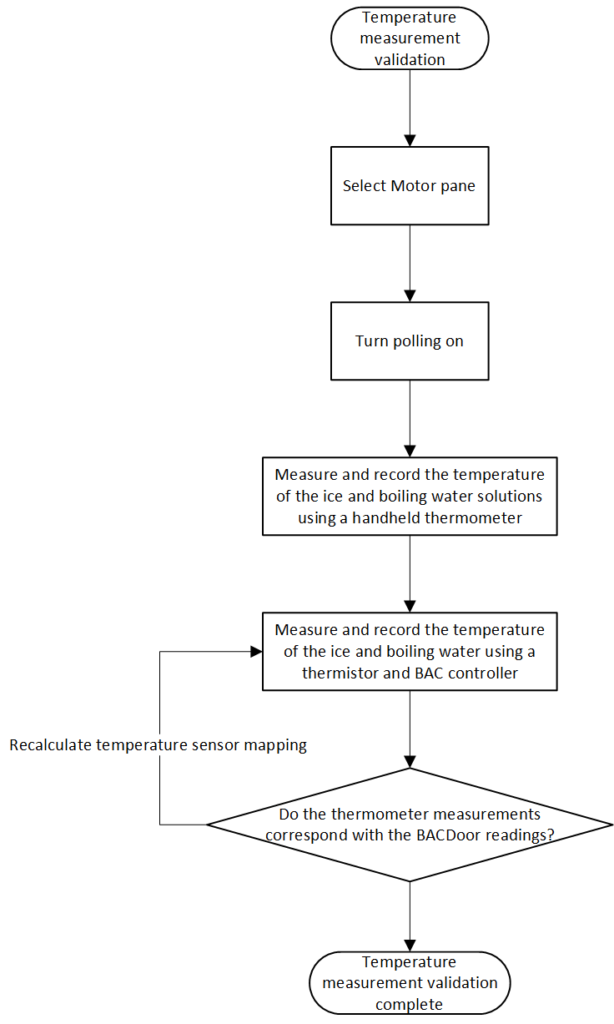
Testing the temperature feedback
The simplest way to test the accuracy of the temperature feedback involves using a hand-held thermometer and two known temperatures such as ice water and boiling water following the steps below. Verify motor temperature in BACDoor™ matches the expected temperature on your thermometer, i.e. ~0 °C for ice water or ~100 °C for boiling water.
Configuration parameters
General configuration
| Name | Description | Units | Address |
| 212bit5 | |||
| 174bit6 | |||
| 174bit7 | |||
| 137 | |||
| 93 | |||
| 94 | |||
| 95 | |||
| 96 | |||
| 97 | |||
| 98 |
Verification
| Name | Description | Units | Address |
| 398 | |||
| 261 |