Throttle
Table of contents
- Introduction
- Warnings
- Required tools
- Supported throttle types
- Throttle input & wiring
- Throttle setup
- Configuration parameters
- Throttle setpoint example
- Troubleshooting
1 – Introduction
Throttle sensors usually provide a 0-5V signal which varies within a specific range depending on the type.
Common throttle inputs vary from 1V to 4V, where anything outside that range can be detected as a fault. I.e.: Missing connections may produce a 0V or 5V signal causing the controller to fault and protect against accidental start-up.
This section will guide you through setting up your throttle.
This section assumes your motor has been set up successfully.
- Getting the motor spinning sensorlessly – eMobility
- Getting the motor spinning sensorlessly – High power
And that you have mapped out your wiring so that you don’t have to rewire inputs later should a conflict arise.
2 – Warnings
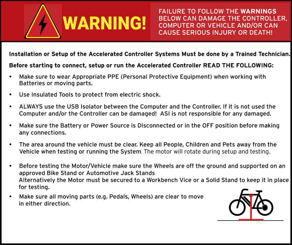
ATTENTION – Indicates a step or procedure required before proceeding to the next step or page.
CAUTION – Indicates a potentially hazardous situation which may result in minor injury or product damage.
WARNING – Indicates a Hazardous situation which if not avoided will result in serious injury/death to person(s) or damage to product and/or equipment.
TIP – Indicates a helpful Tip to make things easier and faster.
3 – Required tools
- Appropriate personal protective equipment (PPE) as required(e.g. Safety glasses, gloves, etc.)
- ASI BACDoor software
- 22 AWG Wire strippers (eMobility)
- 18 AWG Wire strippers (high power)
- Vehicle stand, or motor stand to securely support the vehicle or motor drive wheel off the ground for testing (e.g. Bike stand, jack stands, etc.)
4 – Supported throttle types
- 0-5V Hall based analog throttle
- 0-5V Resistive analog throttle
5 – Throttle input & wiring
A throttle typically has 3 wires: 5V power, GND, and a signal wire. The throttle signal can be wired to use any analog input, typically Throttle/Analog input 1 or ABMS/Analog input 4.
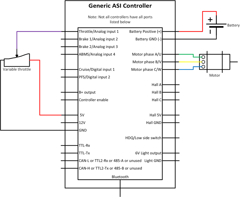
Refer to the peripheral input sources quick sheet in Hardware Inputs to ensure you choose the right input pin and avoid the need to rewire inputs later. For example; if you have a torque sensor, it uses input Throttle/Analog input 1 and throttle would then use ABMS/Analog input 4 instead.
For a two-controller setup (dual-motor), where Master/Slave is not possible, using a single throttle, one controller will provide both the power and ground for the throttle, while both controllers share the signal input.
6 – Throttle setup
WARNING – Ensure vehicle is secured in-case the motor engages unexpectedly while manually configuring your throttle.
TIP – Hover over the information icon for parameter location in BACDoor™ shorthand.
TIP – Make a backup copy of the parameter file often by saving it to file as shown before. It can be sent to ASI for support or you can revert if strange behaviour occurs.
With the throttle connected to the controller
Option A) PC BACDoor™
- Set Control command source to 0 (serial stream) to prevent the motor from accidentally spinning while manually setting the throttle.
- Poll throttle voltage, analog bms soc voltage, brake 1 voltage or brake 2 voltage respectively and make sure the voltage of the analog input connected to your throttle responds to throttle position.
- With the throttle fully off (no throttle applied), read the appropriate analog input and then enter it in Throttle off voltage and press enter.
- With the throttle fully open (full throttle applied), read the appropriate analog input and then enter it in Throttle full voltage and press enter.
- Set Throttle sensor source to your chosen throttle input source and press enter.
- Set Speed regulator mode to 1 for torque mode.
- This step will enable your throttle. Set Control command source to 1 (throttle) and press enter.
- Ensure you do not have any faults, and test the throttle responds accordingly. If not see troubleshooting.
- Press Write to write the changes to the controller.
- In the Parameter drop-down menu, press Save to flash to save the parameters to the controller.
Option B) BACDoor™ Mobile
- Set Control Command Source to Serial to prevent the motor from accidentally spinning while manually setting the throttle.
- Scroll to Throttle Voltage, Analog Bms Soc Voltage, Brake 1 Voltage or Brake 2 Voltage respectively and make sure the voltage of the analog input connected to your throttle responds to throttle position.
- With the throttle fully off (no throttle applied), read the appropriate analog input and then enter it in Throttle Off Voltage and press enter.
- With the throttle fully open (full throttle applied), read the appropriate analog input and then enter it in Throttle full voltage and press enter.
- Set Throttle sensor source to your throttle input source and press enter.
- Set Speed regulator mode to Torque mode.
- This step will enable your throttle. Set Control Command Source to throttle and press enter.
- Ensure you do not have any faults, and test the throttle responds accordingly. If not see troubleshooting.
- Press Save to flash lightning bolt icon, top right, to save the parameters to the controller.
It is recommended that the Throttle fault range, Throttle deadband threshold be left at the factory default setting of 0.2V initially.
If the throttle voltage is less than or greater than throttle voltage source +/- Throttle fault range, this range represents a fault condition. The Throttle deadband threshold value prevents unintended motion from occurring when the throttle is fully closed and ensures a 100% throttle command when fully open.
7 – Configuration parameters
Command inputs configuration
The following parameter is key to configure the main method by which a vehicle is commanded to move.
| Name | Description | Units | Address |
| 208 |
Throttle input configuration
Throttle input configuration uses the following parameters:
| Name | Description | Units | Address |
| 247 | |||
| 213 | |||
| 214 | |||
| 152 | |||
| 151 |
Command levels
The motor command levels can be monitored with the parameters below.
| Name | Description | Units | Address |
| 335 | |||
| 336 | |||
| 325 |
eBike flags
eBike flags are a convenient parameter to monitor when developing a drive system. They indicate what the controller state is when any input is activated.
| Name | Description | Units | Address |
| 327 |
8 – Throttle setpoint example
A sample throttle mapping is shown in the figure below, using the following parameter values:
- Throttle deadband threshold = 0.2V
- Throttle fault range = 0.2V
- Throttle off voltage reading = 0.8V
- Throttle full voltage reading = 4.2V
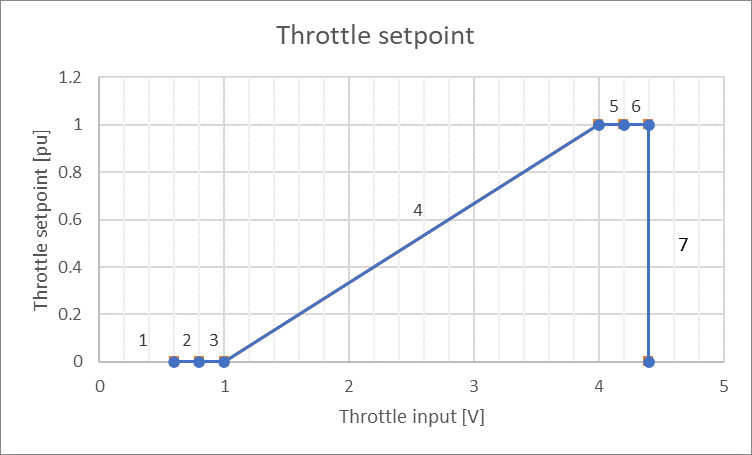
Where
- Less than 0.6V will trigger a fault: Faults, bit 11: Throttle voltage outside range, (flash code 2,4)
- 0.6V to 0.8V is in the throttle fault range
- 0.8V to 1V is in the throttle deadband to prevent unintended motor engagement
- 1V to 4V is the throttle operating window, where 1V = 0% Throttle setpoint and 4V is 100% Throttle setpoint
- 4V to 4.2V is the throttle deadband, ensuring you reach 100% Command output
- 4.2V to 4.4V is in the throttle upper fault range
- Greater than 4.4V will trigger a fault: Faults, bit 11: Throttle voltage outside range, (flash code 2,4)
9 – Troubleshooting
9.1 – Throttle voltage doesn’t change
- Ensure the throttle input is connected to the correct input
- Ensure you are watching the correct input
- Ensure the throttle is connected correctly to power, ground and signal
- Never trust the wire colours: Red is not always 5V, Black is not always GND, White is not always signal
- If it reads 0V, it could be shorted to ground or disconnected if it is a pulled down input.
- If it reads 5V, it could be shorted to power or disconnected if it is a pulled up input.
- If it reads higher, it could be shorted to another power source (B+, 12V, etc.)
9.2 – Brake and cutout enabled
For example, eBike bit 1: Cutout enabled prevents the motor from engaging, this is generally coupled with eBike bit 0: Brake enabled. This means the brake is enabled and is causing the motor to cutout. Solutions include:
- Disconnect your brakes, they may be pulling the brake voltage out of range.
- Set Cutoff brake sensor source to network/4 if not already to stop reading the external brake sensor source and clear the two eBike flags (cutout and brake).
- Poll the chosen Cutout brake sensor source voltage, ensure it is above the Analogue brake full voltage value. If for example, your voltage source is 3.5V and the analogue brake full voltage is 4V, the cutout will be enabled.
9.3 – Faults and warnings
Read parameters faults, faults2, warnings and warnings2 for potential reasons the motor will not engage. See the Faults and warnings troubleshooting for more information.
9.4 – No motor assistance when on the throttle
Are the Rated motor power (Race mode Throttle power) and Rated motor power (Street mode Throttle power), if using alternate power mode, filled in with the motors rated power for throttle. These must be filled in for the throttle to command motor assistance when in their respective power mode.
9.5 – No motor assistance when rolling backwards
If Regeneration battery current limit or Maximum braking torque are set to 0. A slight rolling back of a direct drive vehicle will not allow forward motion until the vehicle is completely stopped. To avoid this type of behaviour set the set these sufficiently high. The Regeneration battery current limit limits battery current used for braking torque and Maximum braking torque limits braking torque motor phase current.