Brakes
Table of contents
- Introduction
- Warnings
- Required tools
- Supported brake sensor types
- Brake sensor input & wiring
- Brake sensor setup
- Configuration parameters
- Troubleshooting
1 – Introduction
Brake sensors can be used to cut motor power or to enable regenerative braking. For example, in emergency situations, as a cut-off source, they will cut any motor assistance when braking, overriding any motor Control command source inputs.
This page concerns the setup of brakes as a cutoff input source. For information on setting up regenerative brakes, see Section 3 – Features: Regen Configuration.
2 – Warnings

ATTENTION – Indicates a step or procedure required before proceeding to the next step or page.
CAUTION – Indicates a potentially hazardous situation which may result in minor injury or product damage.
WARNING – Indicates a Hazardous situation which if not avoided will result in serious injury/death to person(s) or damage to product and/or equipment.
TIP – Indicates a helpful Tip to make things easier and faster.
3 – Required tools
- Appropriate personal protective equipment (PPE) as required(e.g. Safety glasses, gloves, etc.)
- ASI BACDoor software
- 22 AWG Wire strippers (eMobility)
- 18 AWG Wire strippers (high power)
- Vehicle stand, or motor stand to securely support the vehicle or motor drive wheel off the ground for testing (e.g. Bike stand, jack stands, etc.)
4 – Supported brake sensor types
The following pull-down brake sensor types are supported:
- Hall 0-5V signal
- Resistive 0-5V signal
5 – Brake sensor input & wiring
Brakes typically consist of 2 wires. With one wire connected to GND and the other connected to the input pin for pull-down configurations. Or with one wire connected to +5V and the other connected to the input pin for a pull-up configuration.
The brake signal can be wired to use any digital input, typically Brake 1/Analog input 2, but additionally Brake 2/Analog input 3, Cruise/Digital input 1 or PFS/Digital input 2. Note that Brake 1 and Brake 2 are hybrid inputs, these are analog inputs but can be treated as digital inputs as well.
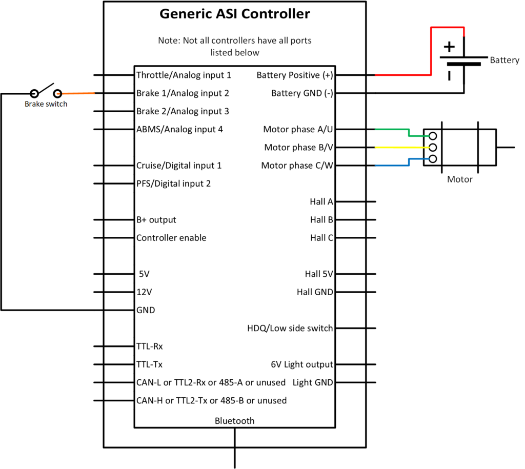
Pull-down brake sensor wiring
Typical pull-down brake sensor setup.
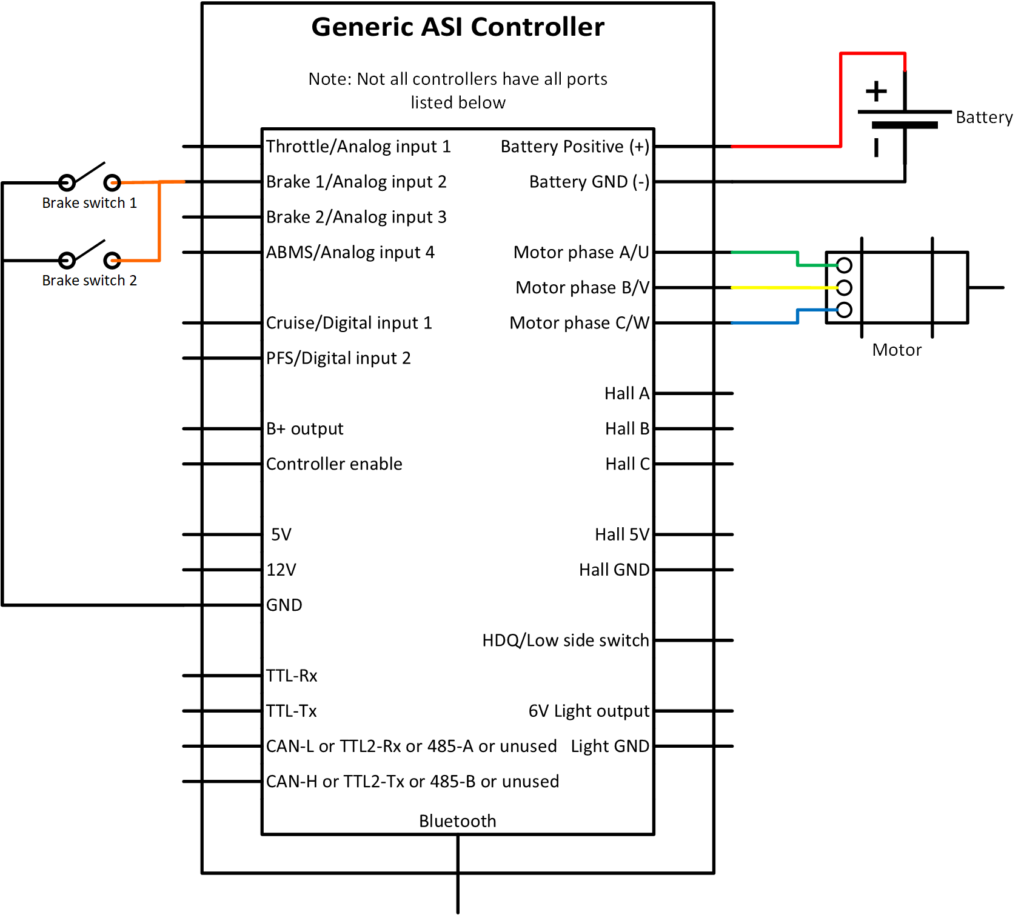
Dual pull-down brake sensor wiring
Typical dual brake, single input, setup. Commonly used on eBikes where either brake, front or back, can be used to cut-off motor power by connecting them in parallel.
6 – Brake sensor setup
WARNING – Ensure vehicle is secured in-case the motor engages unexpectedly while manually configuring your brakes.
TIP – Hover over the information icon for parameter location in BACDoor™ shorthand.
TIP – Make a backup copy of the parameter file often by saving it to file as shown before. It can be sent to ASI for support or you can revert if strange behaviour occurs.
With your brake wired to the controller.
Option A) PC BACDoor™
- If not using input pins Brake 1/Analog input 2 or Brake 2/Analog input 3, skip this step. If using input pins Brake 1/Analog input 2 or Brake 2/Analog input 3, confirm and set Features2 bit6 or bit7 to 1 (high) for Brake 1/Analog input 2 or Brake 2/Analog input 3, respectively, if using pull-down brakes.
- Poll digital inputs and watch that the input the brake is connected to (bit 3 for PFS, bit 4 for Cruise, bit 5 for brake 1, and bit 6 for brake 2 respectively). Opening and closing the brake should result in the bit value alternating between 0 and 1. 0 for open/off and 1 for closed/on.
- Alternatively, confirm that the input voltage changes for Brake 1/Analog input 1 and Brake 2/Analog input 3 by watching brake 1 voltage or brake 2 voltage respectively. For pull-down configuration, the voltage should be nearly 5V when open/off and pull down to nearly 0V when closed/on.
- With the brake sensor source operating as expected. Set the Cutoff brake sensor source to the corresponding input source.
- Poll ebike flags . Bit 0 should be off when the brakes are fully open and on when fully closed. If not, see troubleshooting before continuing.
- Next, if the motor command source is functioning (ex. throttle, pedal or remote). With the motor running (e.g. while on the throttle or pedalling), apply the brakes, ideally to the non-driven wheel, and the motor assistance should be cut. Releasing the brakes while still commanding assistance from the motor should re-engage the motor.
Option B) BACDoor™ Mobile
- If not using input pins Brake 1/Analog input 2 or Brake 2/Analog input 3, skip this step. If using input pins Brake 1/Analog input 2 or Brake 2/Analog input 3, confirm and set Features2 bit6 or bit7 to 1 (high) for Brake 1/Analog input 2 or Brake 2/Analog input 3 respectively if using pull-down brakes.
- Watch digital inputs and watch that the input the brake is connected to (bit 5 for brake 1, bit 6 for brake 2, bit 3 for PFS or bit 4 for Cruise respectively). Opening and closing the brake should result in the bit value alternating between 0 and 1. 0 for open/off and 1 for closed/on.
- Alternatively, confirm that the input voltage changes for Brake 1/Analog input 1 and Brake 2/Analog input 3 by watching Brake 1 voltage or Brake 2 voltage respectively. For pull-down configuration, the voltage should be nearly 5V when open/off and pull down to nearly 0V when closed/on.
- With the brake sensor source operating as expected. Set the Cutoff brake sensor source to the corresponding input source.
- Watch ebike flags . Bit 0 should be off when the brakes are fully open and on when fully closed. If not, see troubleshooting before continuing.
- Next, if the motor command source is functioning (ex. throttle, pedal or remote). With the motor running (e.g. while on the throttle or pedalling), apply the brakes, ideally to the non-driven wheel, and the motor assistance should be cut. Releasing the brakes while still commanding assistance from the motor should re-engage the motor.
7 – Configuration parameters
Brake input source
| Name | Description | Units | Address |
| Cutoff brake sensor source | 248 |
Brake command
These parameters can be watched to verify that the brake is being commanded correctly when opening and closing the brake.
| Name | Description | Units | Address |
| eBike flags | 327bit0 | ||
| brake setpoint | 326 |
Input source & wiring verification
These parameters can be watched to verify the input source is changing and is wired correctly.
| Name | Description | Units | Address |
| 271 | |||
| 272 | |||
| 276bit3 | |||
| 276bit4 | |||
| 276bit5 | |||
| 276bit6 |
8 – Troubleshooting
8.1 – EBike flag bit 0 not changing
- Verify you have the brakes wired correctly. Example: Pull-down brakes connect signal to GND when closed and are open circuit when open. Setting the Features2 bit 6 high for Brake 1 Pull-up enable and/or Features2 bit 7 high for Brake 2 Pull-up enable, pulls the open circuit signal to 5V.
- Verify your input source changes when you open and close the brake sensor.
- Verify your Cutoff brake sensor source is set to the appropriate input.
8.2 – Values not changing when polling/ watching
- Ensure you are connected to the controller. On PC BACDoor™ the Activity lights (Tx&Rx) in the Network notification centre will be flashing continuously while connected. On BACDoor™ mobile, the green light in the top left should be flashing.
- In PC BACDoor™, make sure the poll button is lit. Sometimes you must change back and forth between tabs, such as after you’ve added a new parameter for the application to begin polling again.