Assist Level Configuration
Introduction
Assist levels allow the rider to adjust his maximum power and speed. Depending on the type of displays or buttons that are used these levels can be adjusted.
Assist levels set the assist gain and assist speed limit, these parameters limit the output current/power and active speed limit if in a speed-limiting mode respectively. Their range is 0 to 1.0pu, for 0% and 100% of the active motor output power limit or speed limit respectively.
Assist mode source configuration
0 – None
assist speed limit and assist gain always = 1.0 pu.
1 – Analog
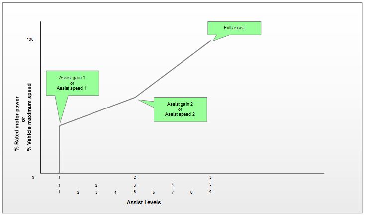
Uses Assist gain 1 and Assist speed 1 as the low assist point and 100% as the high assist point. The assist gain and assist speed limit setpoints are determined based on the analog assist input.
2 – Display
Uses Assist gain 1 through Assist gain 3 and Assist speed 1 through Assist speed 3 as the 3 points about which it interpolates the assist gain and assist speed limit.
Application note: Displays typically send a PWM value, but are not always consistent. Thus, a 3-assist level display may not match 1:1 with the values set above and may use interpolation to determine the assist gain and assist speed limit from that.
This applies to assist levels from displays sending more than 3 “Assist levels”. For example, with 5 assist levels, 1 typically maps to Assist gain 1 and Assist speed 1, 2 will interpolate to a value between Assist gain 1 and Assist gain 2, and Assist speed 1 and Assist speed 2. Etc.
Assist level 0 from the display will result in assist gain and assist speed limit being set to 0 pu, assuming the display sends a PWM value
5 – network gains
Write to speed limit gain and assist limit gain respectively. Renamed Display speed limit command and Display assist level command at some point.
9 – Discrete 9 assist mode
Set Assist gain 1 through Assist gain 9 and Assist speed 1 through Assist speed 9 respectively.
Write to Remote assist mode a value between 0 and 9 to set the assist level and assist speed limit respectively. Note, 0 corresponds to assist level and assist speed limit being set to 0 pu.
Configuration parameters
General
| Name | Description | Units | Address |
| 210 | |||
| 241 | |||
| 219 | |||
| 245 | |||
| 250 | |||
| 1906 | |||
| 1907 | |||
| 1908 | |||
| 1909 | |||
| 1910 | |||
| 1911 | |||
| 241 | |||
| 246 | |||
| 251 | |||
| 1912 | |||
| 1913 | |||
| 1914 | |||
| 1915 | |||
| 1916 | |||
| 1917 | |||
| 253 |
Network values
| Name | Description | Units | Address |
| 500 | |||
| 501 | |||
| 506 |
Setpoints
| Name | Description | Units | Address |
| 329 | |||
| 339 |