Hall Sensor
Table of Contents
1 – Introduction
These instructions are for Hall sensored motors. In this section, we will verify the motor Hall wiring, establish the motors Hall table and the motor Hall offset angle.
Before starting this procedure, you must have already successfully completed Getting the motor spinning sensorlessly – eMobility or Getting the motor spinning sensorlessly – High Power respectively. Having completed getting the motor spinning sensorlessly, you are ready to begin tuning your Halls.
2- Warnings
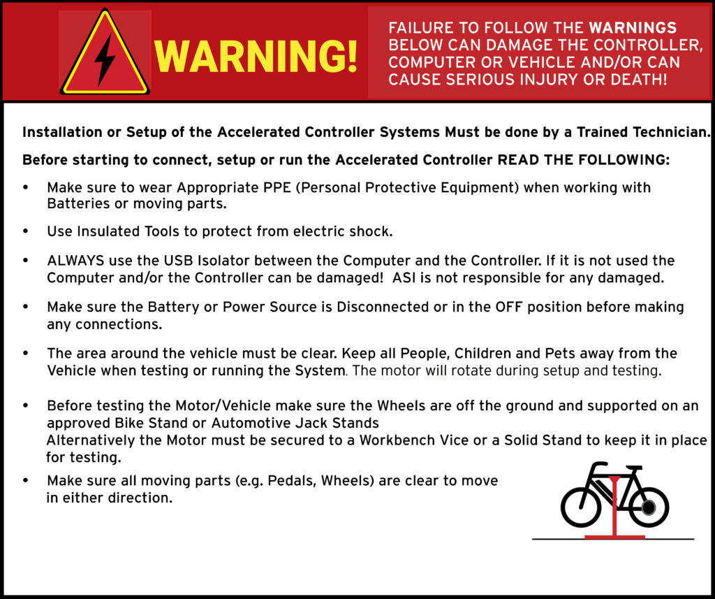
ATTENTION – Indicates a step or procedure required before proceeding to the next step or page.
CAUTION – Indicates a potentially hazardous situation which may result in minor injury or product damage.
WARNING – Indicates a Hazardous situation which if not avoided will result in serious injury/death to person(s) or damage to product and/or equipment.
TIP – Indicates a helpful Tip to make things easier and faster.
3 – Tools required
- Appropriate personal protective equipment (PPE) as required(e.g. Safety glasses, gloves, etc.)
- ASI BACDoor software
- Wire strippers
- Crimpers
- Vehicle stand, or motor stand to securely support the vehicle or motor drive wheel off the ground for testing (e.g. Bike stand, jack stands, etc.)
4 – Connect your Halls
CAUTION – You must only use Hall GND and Hall 5V for powering your Halls and not other components. This is due to the Halls being located in the motor and the significant level of electrical noise it generates.
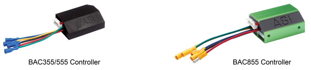
Option A) eMobility (BAC355, BAC555, BAC855)
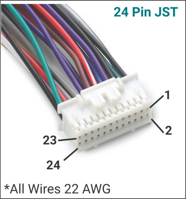
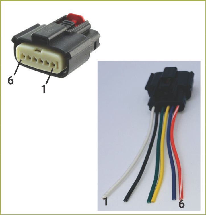
See Table 1 below for the pin numbers, and our evaluation kit wiring harness wire colour, to connect your Halls to the 24-pin JST controller connector.
ATTENTION – Note that it is pins 1, 2, 3, 4 and 6 (Six).
Table 1 – eMobility Hall pin-out
| Pin # | Eval Harness Colour | Function | Specifications & Ratings |
| 1 | Black | Hall GND | 20 mA max |
| 2 | White with Black stripe | Hall 5V Output | 20 mA max |
| 3 | Green | Hall A | 0V ON, 5V OFF |
| 4 | Blue | Hall C | 0V ON, 5V OFF |
| 6 | Yellow | Hall B | 0V ON, 5V OFF |
Option B) High Power (BAC2000, BAC4000, BAC8000)
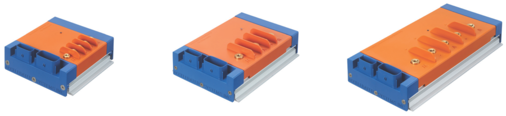
See the table below for the pin numbers, and our evaluation kit wiring harness wire colour, to connect your Halls to the 6-pin Molex connector.
Table 2 – High power Hall pin-out
| Pin # | Eval Harness Colour | Function | Specifications & Ratings |
| 1 | White | Hall 5V Output | 20 mA max |
| 2 | Black | Hall GND | 20 mA max |
| 3 | Green | Hall A | 0V ON, 5V OFF |
| 4 | Yellow | Hall B | 0V ON, 5V OFF |
| 5 | Blue | Hall C | 0V ON, 5V OFF |
5 – Discover your Hall table
WARNING
- The Motor will be spinning in the next steps for up to 20 seconds at 50% of the Rated motor speed (RPM) and high current.
- Make sure all moving parts (e.g. Motor, Pedals, Wheels, etc.) are clear to move in either direction.
- Make sure the motor is securely mounted and the wheels are off the ground.
To stop the motor
- In PC BACDoor™, enter 0 for Motor discovery.
- Or turn off the controller,
- As a last resort, disconnect the battery. This has a high chance of damaging the controller permanently.
CAUTION – Make sure the system is connected to an adequate battery. This test will draw the full rated motor current and can damage the power source if it is inadequate.
TIP – Make a backup copy of the parameter file often by saving it to file as shown before. It can be sent to ASI for support or you can revert if strange behaviour occurs.
ATTENTION – Ensure you have successfully completed Getting the motor spinning sensorlessly – eMobility or Getting the motor spinning sensorlessly – High Power before continuing below.
TIP – Hover over the information icon for parameter location in BACDoor™ shorthand.
In this section, we will read your motor’s Halls, provide you with how to interpret and accept the results.
Option A) PC BACDoor™
Navigate to the Peripheral Configuration tab, select the Basic Motor (Sensored) page. In the Write/Save section, ensure that the motor is configured for sensorless position feedback type by setting the Motor position sensor type to 2. Click Write.
Ensure your wheel is off the ground and able to rotate freely in either direction. This function will cause the motor to spin at half the rated speed for 20 seconds. In the Write (Temp) section of the same page, change Motor discovery mode to 2 and click Write.
Your motor will rotate at 50% rated motor speed as BACDoor™ determines the position of your Halls. Once the motor stops spinning, click Read in the Display Only section of the same page to fill in the auto-discovered values.
Verify the autotune Hall sectors 0 through 7 forms a valid Hall table. A valid Hall table consists of 8 values; -1 can repeat twice, values 0 through 5 should not. A valid Hall table may look like [-1, 0, 4, 5, 2, 1, 3, -1] for example, where starting from the left we have autotune hall sector[0] = -1, autotune hall sector[1] = 0, autotune hall sector[2] = 4, etc.
For example, a Hall table of all -1 is invalid (e.g. [-1,-1,-1,-1,-1,-1,-1,-1]), or a table with more than two -1 values (e.g. [-1, 0, 4, -1, 2, 1, 3, -1]) , or with a value between 0 and 5 inclusive that repeats (e.g. [-1, 0, 4, 5, 2, 2, 3, -1]). See troubleshooting for more information.
With a valid Hall table, copy the autotune hall sector values to the matching Hall sector on the left pane. E.g. autotune hall sector[0] gets copied to Hall sector[0] , autotune hall sector[1] gets copied to Hall sector[1] , etc.
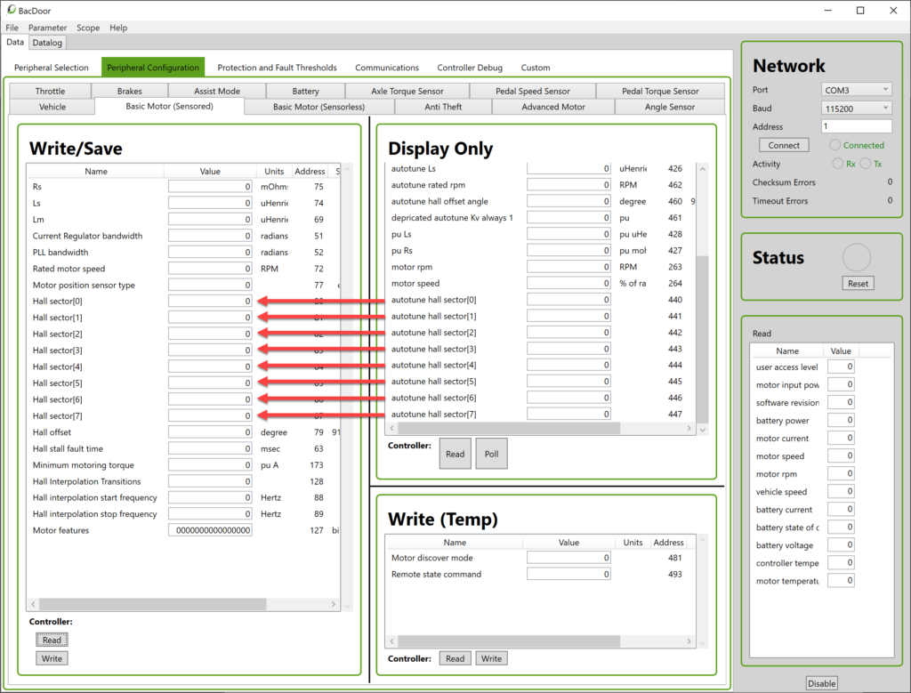
Now, copy the autotune hall offset angle from the Display Only side to Hall offset in the Write/Save section.
Press Write to save your changes to the controller and then select the Parameter drop-down menu and then Save to flash, to preserve settings in the controller after a power cycle.
Now that your Hall sensors are configured, you can change the Motor position sensor type to 0 for Halls only, or 1 for Hall start and sensorless operation above the Sensorless closed loop enable frequency. Click Write.
Option B) BACDoor™ Mobile
With the BACDoor™ app connected to the correct controller. From Live Feed, select the Motor page. Under Basic Motor Configuration, ensure Motor Position Sensor Type is set to Sensorless.
Ensure your wheel is off the ground and able to rotate freely in either direction. This function will cause the motor to spin at half the rated speed for 20 seconds.
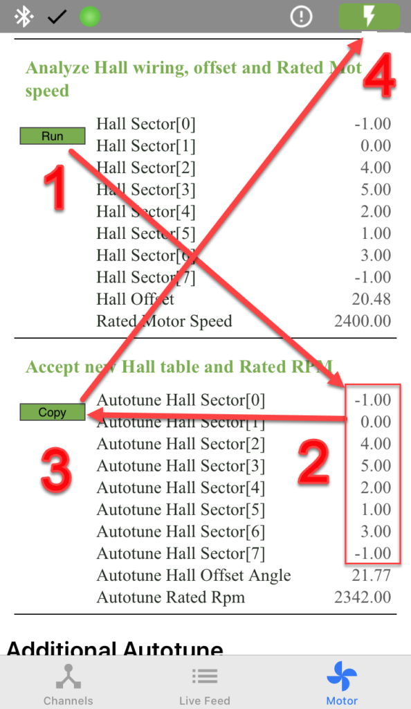
1 – In the Motor Setup section of the same page, press Run under Analyze Hall wiring, offset and Rated Motor speed .
Your motor will turn at 50% rated motor speed as BACDoor™ determines the position of your Halls. Once the motor stops spinning, the Analyze Hall wiring, offset and Rated Motor speed should show the currently saved values, and Accept new Hall table and Rated RPM should populate with the newly measured values.
2 – Verify Autotune Hall Sectors 0 through 7 in the Accept new Hall table and Rated RPM section forms a valid Hall table. A valid Hall table consists of 8 values; -1 can repeat twice, values 0 through 5 should not. A valid Hall table may look like [-1, 0, 4, 5, 2, 1, 3, -1] as an example, where starting from the left we have autotune hall sector[0] = -1, autotune hall sector[1] = 0, autotune hall sector[2] = 4, etc.
For example, a Hall table of all -1 is invalid (e.g. [-1,-1,-1,-1,-1,-1,-1,-1]), or a table with more than two -1 values (e.g. [-1, 0, 4, -1, 2, 1, 3, -1]) , or with a value between 0 and 5 inclusive that repeats (e.g. [-1, 0, 4, 5, 2, 2, 3, -1]). See troubleshooting for more information.
3 – With a valid Hall table, press copy in the Accept new Hall table and Rated RPM section to copy the autotune values to their respective Hall Sectors.
4 – Press the lightning bolt button to Save to flash, to preserve settings in the controller after a power cycle.
Now that your Hall sensors are configured, you can change the Motor position sensor type Motor Position Sensor Type to Hall Based, or Hall start and sensorless run when operating above the Sensorless closed loop enable frequency. Click Write.
6 – Troubleshooting
TIP – Hover over the status light in PC BACDoor™ or go to Live Feed and scroll to the top to Faults and Warnings to see the details of faults or warnings.
6.1 – Hall vs Sensorless position Fault
Your Motor position sensor type is set to 0 (Hall based) or 1 (Hall start and sensorless run) and it is throwing an error as a result. Set this value to 2 (sensorless) for the motor speed autotune.
- Set Motor position sensor type to 2
- Or for mobile set Motor Position Sensor Type to Sensorless.
6.2 Hall table issues
- Hall tables of all -1 indicate the sensors have either no ground, no power, no sensors connected at all, or all of the above. Verify your sensors are connected to Hall 5V and Hall GND. Verify the sensors are connected to Hall A, Hall B and Hall C.
- Hall tables with repeating values or more than two -1 values indicate that one or more of the hall sensors is not connected, verify Hall A, Hall B and Hall C are connected.
- Hall Tables with repeating values may be due to a combination of high rpm and low signal quality, leading to repeating values being read by the controller.
6.3 Motor power
Hall sensor discovery requires that Rated motor power (Race mode Throttle power) be filled in with at least the motors rated power for Analyze Hall wiring, offset and Rated Motor speed to work.