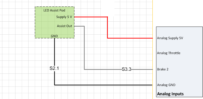
The recommended wiring of an analogue assist pod is shown in the figure below. Only Brake 2/Analogue input 3 is a valid signal input for an analogue assistance device.
Analogue assist setup
With the analogue assist device connected to the controller.
Change assist mode source to 1 (analog)
Poll and read the brake 2 voltage input to measure the analog assist levels.
Enter the level 0 (or low assistance switch position if not a POD) assist voltage (no LEDs on) into Assist low voltage reading
Enter the level 3 (or high assistance switch position if not a POD) assist voltage into Assist high voltage reading
Assist low voltage reading uses Assist gain 1 and Assist speed 1 for the low assist level and linearly interpolates to 100% assist at Assist high voltage reading.