Regen Braking
Table of Contents
- Introduction
- Regen brake wiring
- Regen braking implementation
- Setup instructions
- Regen brake tuning
- Configuration parameters
1 – Introduction
Electric motors, when used in reverse, function as generators. ASI controllers can convert the vehicle’s kinetic energy into electrical energy to recharge the batteries and reduce wear on mechanical components (brake pads) while slowing the vehicle down.
Common regen braking inputs include on/off switches which command either 0 or 100% of the available regen braking torque, or variable 0-5V signals to linearly request from 0 to 100% of available regen braking torque.
Remote control (network) of regen braking is not covered in this section. Please contact ASI support for information if required.
2 – Regen brake wiring
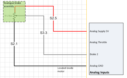
A typical regen brake source is either on/off (2 wires): signal and GND. Or variable (3 wires): 5V power, GND and a signal wire.
Physical Regen brake source‘s include: Brake2/Analog input 3 and Brake1/Analog input 2.
An example is shown in the figure below.
3 – Regen braking implementation
In ASI controllers, battery regenerative current (motor current-driven back into the battery) is always present even if regen braking options are not enabled.
Regen current is always monitored. For instance, a direct drive motor moving backwards while enabled, even slightly, will cause regen currents. To protect the battery from being overcharged the controller can limit this current by setting the Regeneration battery current limit parameter.
Note that, if a controller’s Regeneration battery current limit parameter is set to 0%. Even a slight rollback of a direct drive vehicle will not allow forward motion until the vehicle comes to a complete stop. To avoid this type of behaviour set this parameter to at least 20%.
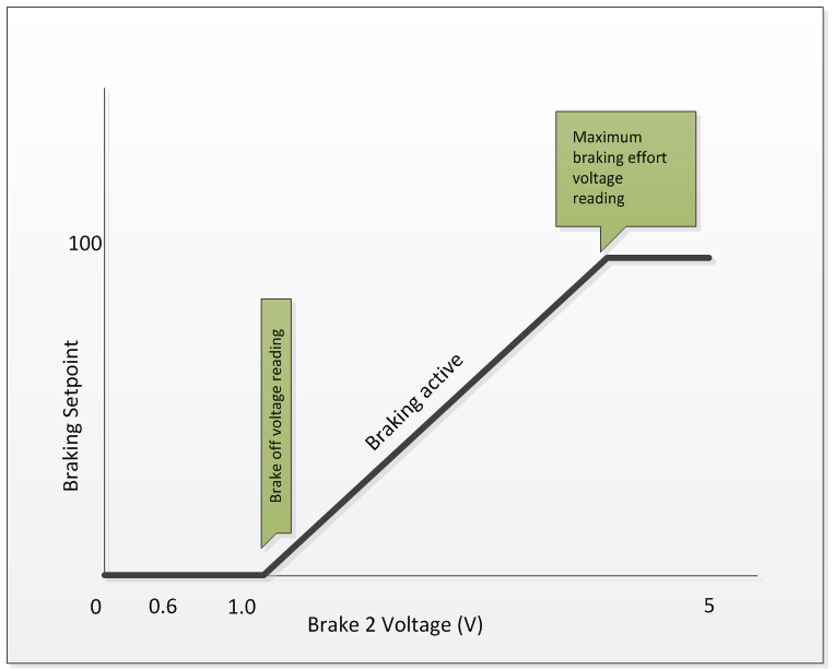
Regen brake setpoint is determined by the Analogue brake off voltage and Analogue brake full voltage as shown in the figure below. When the brake setpoint is 0, there is no regen braking and when it is 1.0 there is 100% of available regen braking. Note that for digital inputs, the input source is often pulled up and the off voltage is 4V (brake setpoint = 0) and 1V (brake setpoint = 1.0) for full brakes since the circuit generally pulls to ground. For analogue regen (ex: using a throttle), generally, the source is not pulled up and like a throttle, the off signal voltage is around 0.9V to 1.2V (brake setpoint = 0) and full braking signal voltage is around 3.9V to 4.2V (brake setpoint = 1.0) .
The brake setpoint then maps to the Maximum braking torque output as shown in the figure below.
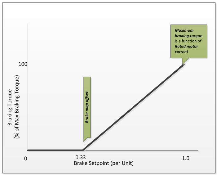
For a brushless DC motor, torque is approximately proportional to the motor phase current. This is why we set Maximum braking torque as a function of the Rated motor current. As an example, if Rated motor current = 50 Amps and Maximum braking torque = 30%. Then when the braking setpoint is equal to 1.0 (per Unit), the braking “torque” will be equal to 15 Amps.
Note that regen braking becomes ineffective at low speeds and should not be used as the sole source of braking. It should only be used in addition to a functioning mechanical braking setup.
4 – Setup instructions
In order to set up the regen braking via an ON/OFF brake switch wired to GND and source, follow the steps below.
- Set Regeneration battery current limit percentage of your battery’s peak charging/regen current relative to your Rated motor power divided by Rated system voltage.
- Example: Your Rated motor power is 2880W, regen is 45A peak and your nominal battery voltage (Rated system voltage) is 48V. Your regeneration battery current limit is = 45A/ (2880W/48V) = 0.75 or 75%.
- Set Features bit 4 Regen braking enable to 1, or ON.
- Set Regen brake source to the desired input source (Brake 1 or Brake 2).
- If not already, set Features2 bit 6 Brake 1 Pullup enable or bit 7 Brake 2 Pullup enable to 1, or ON, to pull up your chosen Regen brake source respectively.
- Set the Maximum braking torque to the desired percent of Rated motor current.
- Start out conservatively, ex. 10%, to understand the braking effect and not risk having too much braking torque and skidding, causing a possible crash. See Regen brake tuning below
- Set Analogue brake off voltage to 4V and Analogue brake full voltage to 1V.
- Note: Analogue braking does use and apply the Throttle deadband threshold.
- Verify that the Brake setpoint follows the brake input: e.g. OFF brakes = 0 at Analogue brake off voltage – Throttle deadband threshold and ON brakes = 1.0 at Analogue brake full voltage + Throttle deadband threshold, if using the voltages at #5 above.
- Move on to Regen brake tuning below.
5 – Regen brake tuning
Dialling in the regen braking feel is an iterative process. As such, parameter and mechanical adjustments may need to be repeated several times before vehicle behaviour under braking performs to your satisfaction. The Maximum braking torque and the Positive braking torque ramp are the two parameters to be adjusted to change the feel of the bike under braking. Where Maximum braking torque affects total braking torque available as a percentage of Rated motor current. Positive braking torque ramp adjusts how fast braking torque is increased from 0 to full braking torque.
The Negative braking torque ramp can be used to adjust how fast the commanded braking torque goes from full braking torque to no commanded braking torque.
Regen brake speed can be used to set the lower regen braking speed limit, as regen braking becomes ineffective at low speeds and can cause the braking feel to be inconsistent.
6 – Configuration parameters
Primary regen braking configuration parameters
| Name | Description | Units | Address |
| Regen brake source | 249 | ||
| Features bit 4 | Regen braking enable | 212bit4 | |
| Positive braking torque | 224 | ||
| Negative braking torque | 225 | ||
| Analogue brake off voltage | 216 | ||
| Analogue brake full voltage | 215 | ||
| Maximum braking torque | 154 | ||
| Regen brake speed | 206 | ||
| Regeneration battery current limit | 156 |
Parameters to watch regarding regen braking setup
| Name | Description | Units | Address |
| calculated battery current braking limit | 397 | ||
| negative battery limit | 387 | ||
| regen phase current limit | 333 | ||
| phase regen current power limit | 309 |